
- Home
- >
Electrode Preparation
- >
Battery Tab Welder
- >
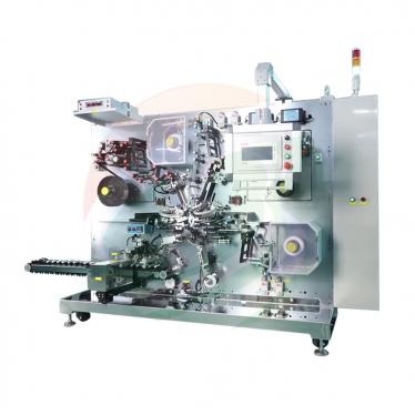
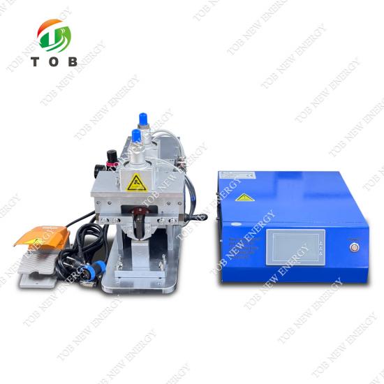
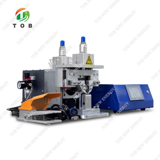
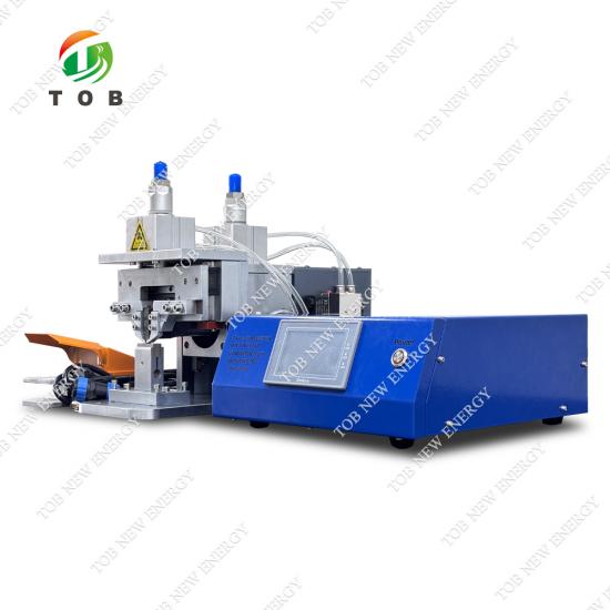
20kHz Ultrasonic Metal Welding Machine for Battery Electrode and Multi-Layer Tab Welding
Categories
Hot Products
Loading...

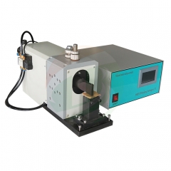
20kHz Ultrasonic Metal Welding Machine for Battery Electrode and Multi-Layer Tab Welding
Brand:
TOB NEW ENERGYitem no.:
TOB-20K-1500Worder(moq):
1setPayment:
L/C,T/Tproduct origin:
Chinashipping port:
XIAMEN
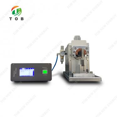
TOB-20K-1500W 20kHz Ultrasonic Metal Welding Machine for Battery Electrode and Multi-Layer Tab Welding
Product Overview and Ideal Applications
An ultrasonic metal welding machine uses high-frequency vibratory energy to join thin metal workpieces without melting the base material. The TOB-20K-1500W generates 20 kHz mechanical oscillations through a piezoelectric transducer, amplifies the displacement via a booster and horn, and delivers the energy to the weld interface under controlled pneumatic pressure. The high-frequency scrubbing action at the faying surfaces breaks up oxide layers and creates a solid-state bond. Unlike resistance or laser welding, ultrasonic welding produces no spatter, no bulk melting, and no heat-affected zone—critical advantages when welding ultra-thin battery foils that would perforate under other methods.
The system is built around a full‑digital ultrasonic generator sourced from Germany, which provides intelligent frequency tracking, constant‑amplitude output that compensates for mains voltage fluctuations, and selectable welding modes including energy mode, time mode, and intelligent time mode. The welding head uses imported high‑speed steel (Yishengbai, Bohler-Uddeholm grade) with two independent usable faces, each carrying a micro‑textured pattern engineered to grip and bond aluminium and copper foils as thin as 0.012 mm without tearing. A high‑definition touch‑screen interface stores over 100 welding records, supports custom cloud services for OEE tracking and remote diagnostics, and provides real‑time alarm protection for over‑voltage, over‑current, over‑temperature, and weld overload.
Ideal for:
- Lithium-ion battery production lines welding cathode aluminium tabs (0.012 mm foil to 0.2–0.5 mm tab) and anode copper tabs (0.008–0.012 mm foil to 0.2–0.4 mm nickel‑plated copper tab).
- Pouch cell assembly: multi‑layer lamination welding (10–45 layers), butterfly welding, and aluminium-to‑nickel transition joints.
- Cylindrical cell manufacturing: cap-to‑aluminium‑strip single‑point welding, bottom aluminium shell to aluminium‑nickel composite tape welding.
- Automotive wire harness, solar panel interconnection, copper tube sealing, and glass-plate solar welding applications requiring a clean, oxide‑breaking solid‑state bond.
- Any production environment replacing consumable‑intensive resistance welding or slow laser spot welding with a rapid, repeatable, and documentation‑ready ultrasonic process.

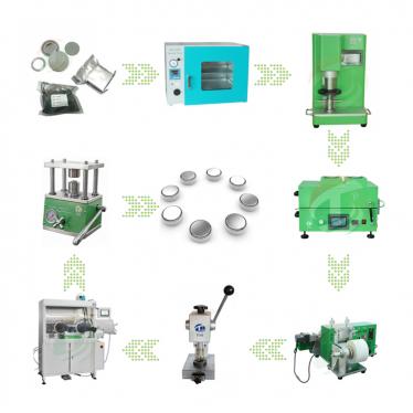
Where Ultrasonic Welding Fits in Battery Cell Assembly
Ultrasonic welding takes place during thecell assemblystage of lithium-ion battery manufacturing, after electrode coating and slitting or electrode punching, and before electrolyte filling. For a cylindrical cell (e.g., 18650 or 21700), the aluminium cathode tab is welded to the uncoated foil edge or to a current‑collector strip, and the nickel‑plated copper anode tab is welded similarly. The cell cap is then joined to the aluminium strip with a single‑spot ultrasonic pulse. For pouch cells, multiple layers of cathode or anode foils are gathered into a stack and welded to a single thicker tab in a multi‑layer lamination weld—commonly 10 to 45 layers depending on cell capacity and the specific welding length.
The weld must simultaneously satisfy three demanding requirements: bond strength approaching that of the parent material, no burn‑through or foil thinning that would create a high‑resistance point or a mechanical weak spot, and a weld cycle time under one second to match the production cadence. The TOB-20K-1500W achieves this with precisely delivered ultrasonic energy that breaks the tenacious oxide films on aluminium and copper surfaces while keeping the bulk material temperature far below the melting point.
Process best practices from real production environments:
- Surface preparation: Aluminium foil oxidises within minutes of air exposure. Wipe foil surfaces with anhydrous isopropyl alcohol immediately before loading into the welding fixture. Do not use abrasive scouring pads—they remove material and create debris that can embed in the weld interface.
- Horn-to-anvil alignment: The upper horn pattern (straight‑line or cross‑hatch "rice" pattern) must fully contact the tab stack, and the lower anvil pattern (mesh or reticulate) must support the bottom foil without tilting. Even a 0.05 mm angular misalignment can produce a partial bond that passes visual inspection but fails during cell formation cycling.
- Horn face cleaning interval: After approximately 500–1000 welds on aluminium, transferred metal can begin to adhere to the horn face. Clean with a soft brass brush or a dedicated cleaning fixture. Never use steel tools—scratches become stress risers and lead to premature horn cracking.
- Pressure optimisation: The pneumatic cylinder (AIRTAC SDA63×20, 63 mm bore, 20 mm stroke) delivers up to 6 kg/cm² working pressure. For 0.012 mm aluminium foil, start at 2–3 kg/cm². For multi‑layer pouch stacks (20+ layers), 4–5 kg/cm² is typical. Excessive pressure flattens the foil microstructure and paradoxically reduces bond strength; insufficient pressure allows sliding and surface galling. The optimum pressure is indicated when the edge of the welding section is indented 1–5 mm below its original plane.


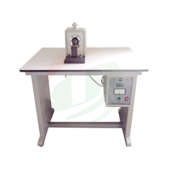
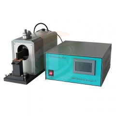
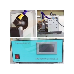
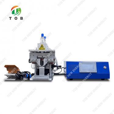
Ultrasonic welding of battery tab
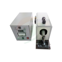
Ultrasonic welding of copper wire and nickel strips
How the TOB-20K-1500W Ultrasonic Welding System Works
Energy conversion and deliveryThe system starts with the ultrasonic generator, a 1500 W digital unit built with IGBT power modules and a separately excited oscillation circuit. It converts 50/60 Hz AC mains power into a precisely controlled 20 kHz electrical signal. This signal drives a piezoelectric transducer (German Tech wafer, model X20) housed in the welding head, which transforms the electrical oscillations into mechanical vibrations of the same frequency.
The mechanical vibration passes through a booster (variable‑amplitude horn, model Y20) that amplifies the displacement to a usable half‑cycle amplitude of 20–40 µm. The amplified motion reaches the welding horn, machined from imported high‑speed steel (Yishengbai material), which transmits the oscillatory shear force directly into the metal stack clamped between the horn and the lower anvil.
The welding event (step by step)
- Squeeze phase (0.02–10 s, programmable): The pneumatic cylinder lowers the welding head. The horn contacts the top workpiece and builds pressure to the set value. The linear guide system (SY linear sliders, 20 mm stroke) ensures vertical, wobble‑free descent regardless of the speed setting—the rise and fall rates are independently adjustable for precise positioning.
- Ultrasonic pulse (0.01–2.0 s): With pressure stabilised, the generator applies the ultrasonic burst. The horn face scrubs laterally against the top metal layer at 20′000 cycles per second, while the lower layers remain stationary against the anvil. This differential motion generates localised frictional heat and intense plastic deformation specifically at the interfaces. Oxide films—the barrier that prevents conventional fusion welding—are fragmented and dispersed into the bulk, exposing clean metal. Under the combined influence of atomic diffusion and plastic flow, a solid‑state metallurgical bond forms. The process does not melt the bulk metal; instead, metal softening at the interface permits the characteristic layer‑by‑layer penetration without blackening or burn‑through.
- Hold phase (several seconds): After the ultrasonic energy stops, the pneumatic pressure is maintained briefly to allow the bond to consolidate and solidify under compression, forming a robust molecular‑level joint. Weld strength approaches that of the original material.
- Return: The solenoid valve (AIRTAC 24V210-10) exhausts the cylinder, and the head retracts to the home position, ready for the next part.
Intelligent control that separates this machine from simpler welders
- Automatic frequency tracking (±20 Hz, search range 19.0000–21.0000 Hz): During continuous production, the transducer and horn heat up, causing their mechanical resonant frequency to drift. The generator continuously detects this shift and re‑locks to the new resonance in real time without any manual intervention. After a horn change or re‑grinding, the system performs a self‑diagnostic at power‑on and automatically locks to the new resonance—no tedious manual tuning like "searching for a radio station," a process still required on many competing machines.
- Constant‑amplitude function: When the mains supply fluctuates between 215 V and 238 V, the generator automatically compensates the output voltage so that the horn amplitude stays constant. This ensures that the hundredth weld of a shift is identical to the first, irrespective of factory power variations.
- Multi‑mode termination: Energy mode stops the pulse when a pre‑set Joule target is reached (best for thick tab‑to‑tab welds where total heat input must be controlled). Time mode runs for a fixed duration (best for high‑speed repetitive single‑spot welding). Intelligent time mode analyses the ultrasonic feedback in real time, identifies the moment of complete interfacial bonding, and terminates the pulse—maximising strength while avoiding excess vibration that could fatigue the foil.
- Segmentable amplitude (1%–100% within 0–100 ms): For delicate ultra‑thin foils, you can program a gentle initial engagement at low amplitude, by a ramp to full amplitude for bonding, and then a taper. "The machine runs exactly the way you want it to run"—a phrase our engineers use with customers.
Key Engineering Advantages for Battery Tab and Foil Welding
- German‑Sourced Digital Ultrasonic System with Automatic Frequency ControlThe transducer uses piezoelectric crystals from German Tech, matched with a fully digital generator built on IGBT modules and a separately excited oscillation circuit. This architecture delivers inherently stable, low‑noise power conversion. Unlike analog generators that require manual frequency tuning and drift with temperature, the TOB system self‑calibrates at start‑up and continuously tracks resonance during operation. The practical result: after replacing a horn or re‑grinding a worn face, the machine locks to the new resonance within seconds with no operator adjustment required—a capability that competing systems in the market often lack, relying instead on a manual "search" procedure analogous to tuning an old radio.
- Layer‑by‑Layer Penetration Without Burn‑Through or BlackeningThe combination of precise amplitude control (20–40 µm half‑cycle), adjustable pressure (0.3–6 kg/cm²), and time resolution (down to 0.01 s) enables true layer‑by‑layer bonding through the entire foil stack. The specification explicitly requires "no blackening," meaning the weld interface remains oxide‑free and the metal does not reach the oxidation temperature. For a 20‑layer aluminium stack welded to a 0.4 mm tab, every layer is joined individually, and the outermost foil remains structurally intact. This directly impacts cell reliability: a partially burnt weld may pass initial QC but develop high resistance during cycling.
- Three Welding Modes for Process FlexibilityThe generator offers energy mode, time mode, and intelligent time mode—each suited to different joint geometries. Energy mode excels at thick multi‑tab welds where total heat input governs quality. Time mode is ideal for high‑speed repetitive single‑spot welding on cylindrical cell lines. Intelligent time mode, unique to this generator, monitors the collapse of the interfaces in real time and automatically terminates the pulse when optimal bonding is achieved, regardless of slight variations in foil thickness or surface condition. This mode is particularly effective for dissimilar metal joints (Al‑to‑Ni) where a fixed energy or time may either under‑weld the nickel side or over‑weld the aluminium side.
- Segmentable Amplitude: 1%–100% Within a 100 ms WindowThis feature gives process engineers very fine control over the weld profile. For extremely fragile 0.012 mm aluminium foil, the amplitude can start at 20% for the first 10 ms (to establish contact without tearing), ramp to 80% over the next 40 ms (to break oxides and begin bonding), and hold at 60% for the remaining 50 ms (to consolidate without over‑heating). A fixed‑amplitude welder simply cannot achieve this level of control, and the difference is visible in both the weld cross‑section and the pull‑test data.
- 100+ Weld Record Storage with Cloud‑Ready Data LoggingThe touch‑screen interface stores over 100 parameter sets and weld histories, each containing amplitude, energy, time, and alarm information. Custom cloud services enable remote OEE monitoring, fault alerts, and traceability for quality audits. When an automotive customer needs to demonstrate that every weld on a particular cell lot was performed within specification, this data is immediately retrievable.
- Robust Mechanical Design for 100′000+ Weld LifeThe welding horn is made from imported high‑speed steel (Yishengbai, a Bohler-Uddeholm grade) and features two independent usable faces, effectively doubling the service interval. The anvil uses a mesh pattern optimised for gripping thin foils without cutting. The linear guide system (SY brand, two sets of linear sliders, 20 mm nominal size) and the pneumatic actuator (AIRTAC SDA63×20 cylinder with AIRTAC 24V210-10 solenoid valve) are specified for industrial duty cycles. The overall equipment design life is 8–10 years, supported by a one‑year warranty on all major components (transducer, booster, horn, main board, output transformer, chip processor from American ID company, cables) with the horn face and base wear being the only exclusions.
- Comprehensive Protection SystemsThe generator continuously monitors: supply voltage (operating band 215–238 V, with automatic compensation inside this range), over‑current (IGBT protection), over‑temperature (internal power transistor auto‑shutdown at 60 °C), unstable mains frequency (automatic compensation), and weld overload (signal feedback that prevents damage to the transducer and horn). EMI/EMC performance is rated as "strong anti‑interference capability," important when the welder operates adjacent to motor drives or other power electronics in a battery production line.


Complete Technical Specifications
Ultrasonic Generator and Control System
|
Parameter |
Specification |
|
Frequency |
20 kHz, automatic tracking range ±20 Hz, display search range 19.0000–21.0000 Hz |
|
Power |
1500 W (selectable 1000 W) |
|
Frequency control |
Built‑in adjustable, fully digital |
|
Power stage |
IGBT modules, separately excited oscillation circuit |
|
Amplitude control |
Stepless adjustable, 1%–100%, segmentable within 0–100 ms window |
|
Constant‑amplitude function |
Yes—compensates for mains voltage fluctuation within 215–238 V |
|
Welding modes |
Energy mode, time mode, intelligent time mode (selectable) |
|
Welding time range |
0.01–2.0 s |
|
Squeeze time range |
0.02–10 s (programmable) |
|
Time adjustment range (general) |
0–60 s |
|
Parameter storage |
Yes, with customisable recall; >100 welding records |
|
Cloud service |
Customisable |
|
Controller |
Microprocessor‑based (American ID company chipset) |
|
Protections |
Over‑voltage (215–238 V band), over‑current, overload, over‑temperature (60 °C auto‑protect), unstable mains frequency auto‑compensation, weld overload signal feedback |
|
EMI/EMC |
Strong anti‑interference capability |
|
Screen |
High‑definition touch screen with intuitive graphical interface |
|
Display |
Dual display: set temperature and measured temperature |
|
Generator dimensions |
Approx. 360 mm × 340 mm × 150 mm |
|
Supply voltage |
AC 220 V, 50/60 Hz |
Welding Head, Transducer, and Pneumatic System
|
Parameter |
Specification |
|
Transducer |
Model X20, German Tech piezoelectric wafers |
|
Transducer matching tolerance |
Frequency difference ≤400 Hz, impedance difference ≤4 Ω, capacitance difference ≤400 pF |
|
Transducer insulation resistance (to shell) |
≥30 MΩ |
|
Booster |
Model Y20 |
|
Horn material |
Imported high‑speed steel (Yishengbai, Bohler-Uddeholm grade) |
|
Horn length |
≥130 mm |
|
Number of usable horn faces |
2 |
|
Horn installation direction |
Transverse (horizontal) |
|
Horn face pattern |
Upper horn: straight‑line or cross‑hatch ("rice") pattern; Lower anvil: mesh pattern |
|
Weld spot height (pattern depth) |
0.8 mm (adjustable according to product process) |
|
Height of welding surface from horn |
>5 mm (adjusted according to product height) |
|
Amplitude adjustable range |
Half‑cycle 20–40 µm |
|
Head vertical stroke |
20 mm (cylinder stroke), linear guide control |
|
Head rise/fall speed |
Adjustable, accurately controlled |
|
Upper/lower position control |
Accurate positioning |
|
Cylinder |
AIRTAC SDA63×20, bore 63 mm × stroke 20 mm |
|
Solenoid valve |
AIRTAC 24V210-10 |
|
Linear guide |
SY brand, linear slider 20, 2 sets |
|
Working pressure |
0.3–6 kg/cm² (min 0.3, max 6 kg/cm²) |
|
Input air supply |
Dry compressed air, 7–8 kg/cm² (bar) |
|
Air inlet |
Quick‑connect, Ø8 mm |
|
Horn face life |
≥100′000 welds |
Applicable Materials and Cell Configurations
|
Application |
Specification |
|
Cathode substrate (current collector foil) |
Aluminium foil, thickness 0.012 mm |
|
Cathode tab material |
Aluminium tab, thickness 0.2–0.5 mm |
|
Anode substrate (current collector foil) |
Copper foil, thickness 0.008–0.012 mm |
|
Anode tab material |
Nickel‑plated copper / nickel tab, thickness 0.2–0.4 mm |
|
Pouch cell max. laminated layers |
10–45 layers (depending on weld length) |
|
Weld spot length |
20 mm (customisable) |
|
Weld spot width |
3 mm (customisable) |
|
Welding mode for tabs |
Transverse (crosswise; customisable) |
|
Weld quality requirement |
No weld penetration, no missed weld, firm bonding, layer‑by‑layer penetration, no blackening |
|
Weld cycle time |
Within 1 s |
|
Number of weld spots |
Designed according to welding process |
|
Welding type |
Single‑point |
Machine Dimensions and Weight
|
Item |
Dimension / Weight |
|
Overall dimensions |
Approx. 900 mm × 600 mm × 750 mm |
|
Head dimensions |
Approx. 500 mm × 310 mm × 620 mm |
|
Generator cabinet dimensions |
Approx. 360 mm × 340 mm × 150 mm |
|
Packing dimensions |
Approx. 1000 mm × 600 mm × 800 mm |
|
Total weight |
Approx. 50 kg |
Component and Spare Parts List
|
No. |
Assembly |
Component |
Spec / Model |
Manufacturer |
Qty |
Warranty |
|
1 |
Cable |
High‑frequency cable |
– |
– |
1 pc |
1 year |
|
2 |
Cable |
High‑frequency cable |
– |
– |
1 pc |
1 year |
|
3 |
Cable |
Output control cable |
Multi‑core |
– |
1 pc |
1 year |
|
4 |
Vibration system |
Transducer |
X20 |
German Tech (wafer) |
1 pc |
1 year |
|
5 |
Vibration system |
Booster (variable‑amplitude horn) |
Y20 |
– |
1 pc |
1 year |
|
6 |
Vibration system |
Welding horn |
20 |
Yishengbai imported material |
1 pc each (positive/negative) |
1 year (wear excluded) |
|
7 |
Vibration system |
Flange plate |
– |
– |
1 set |
1 year |
|
9 |
Control box |
Main board |
– |
– |
1 pc |
1 year |
|
10 |
Control box |
Output transformer |
– |
– |
1 pc |
1 year |
|
12 |
Control box |
Chip processor |
– |
American ID company |
1 set |
1 year |
|
13 |
Fixture |
Upper die setting sleeve |
– |
– |
– |
– |
|
14 |
Fixture |
Base |
– |
– |
1 set |
1 year (wear excluded) |
|
15 |
Frame |
Machine frame |
HY |
– |
1 set |
1 year |
|
16 |
Frame |
Linear guide |
Linear slider 20 |
SY |
2 sets |
1 year |
|
17 |
Frame |
Cylinder |
SDA63×20 |
AIRTAC |
1 set |
1 year |
|
18 |
Frame |
Solenoid valve |
24V210-10 |
AIRTAC |
1 set |
1 year |


Common Ultrasonic Welding Defects and Practical Troubleshooting
The following issues are regularly encountered in battery tab welding. The table explains how the TOB-20K-1500W's features directly help diagnose and resolve each one.
|
Problem |
Possible Cause |
How TOB-20K-1500W Helps / Recommended Action |
|
Weak bond / low pull‑strength (peeling open easily) |
Insufficient energy, amplitude too low, or oxide layer not fully broken. |
Increase energy setpoint in small increments (5 J). Verify amplitude is at least 70–80% for aluminium. Ensure foils were cleaned with IPA before welding. The constant‑amplitude function guarantees that the set amplitude is actually delivered regardless of mains fluctuation. |
|
Foil perforation or burn‑through (weld penetration) |
Energy too high, amplitude excessive relative to foil thickness, or pressure too low causing slippage and local over‑heating. |
Reduce energy, or switch to intelligent time mode which auto‑terminates at bond completion. Increase pneumatic pressure to 3–4 kg/cm² to improve coupling. Check horn‑to‑anvil parallelism. Spec requires absolutely no weld penetration. |
|
Aluminium sticking to horn face / metal transfer |
Insufficient amplitude causing sliding friction rather than bonding, or excessive weld time at low amplitude. |
Clean horn face with a soft brass brush. Increase amplitude slightly and reduce time. The segmentable amplitude function allows a gentle initial engagement to prevent galling. |
|
Weld quality degrades over a production shift |
Horn heating causes frequency drift; or horn face pattern wears below effective depth. |
Verify that automatic frequency tracking is active (it always is by default on this system—no manual intervention needed). If horn pattern depth is below 0.5 mm, rotate to the second usable face or re‑grind. Monitor transducer temperature; the system keeps the vibration group temperature at the minimum possible level. |
|
Loud squeal or abnormal noise during weld |
Resonance mismatch, loose mechanical joint in the vibration stack, or part not firmly supported on the anvil. |
Tighten all mechanical connections (horn, booster, transducer) to specified torque. Ensure the workpiece is fully flat on the anvil. Run the system's automatic frequency search once. The separately excited oscillation structure is inherently more stable than self‑excited designs in avoiding off‑resonance operation. |
|
Generator overload alarm |
Over‑current due to damaged transducer, cracked horn, or extreme part geometry. |
Check transducer insulation resistance—spec requires ≥30 MΩ to shell. Inspect the horn for micro‑cracks using dye penetrant. The overload protection signal feedback prevents catastrophic damage and provides a fault code for quick diagnosis. |
|
Inconsistent weld quality across shifts |
Different operators setting different parameters, or mains voltage variation. |
Store the validated recipe in the parameter memory (>100 records). Lock the recipe to prevent unauthorised changes. The voltage protection system automatically compensates for supply variations between 215 V and 238 V so that output power and frequency are unaffected. |
Recommended Welding Parameters for Common Battery Joints
These starting‑point recipes were developed using a TOB-20K-1500W with a standard straight‑line upper horn pattern and mesh anvil. All assume proper foil cleaning with IPA and ambient temperature 20–30 °C.Fine‑tune to your specific material, foil supplier, and production speed.
|
Joint Type |
Material Stack‑Up |
Welding Mode |
Energy / Time |
Amplitude |
Pressure |
Notes |
|
Single Al tab to Al foil (cathode) |
Al tab 0.3 mm + 1 layer Al foil 0.012 mm |
Energy |
50–70 J |
80 % |
2.5–3.0 kg/cm² |
Use straight‑line horn pattern to avoid foil tearing. Weld spot 20 mm × 3 mm standard. |
|
Single Ni‑plated Cu tab to Cu foil (anode) |
Ni‑Cu tab 0.2 mm + 1 layer Cu foil 0.010 mm |
Energy |
80–100 J |
85 % |
3.0 kg/cm² |
Copper requires higher energy than aluminium. Ensure the tab is nickel‑plated, not bare copper. |
|
Multi‑layer pouch tab (20 layers Al) |
20 layers Al foil 0.012 mm + Al tab 0.4 mm |
Time |
0.6–0.8 s |
90 % |
4.0–5.0 kg/cm² |
Pre‑align foil stack in a fixture. Use a longer weld spot (20 mm) to distribute energy across all layers. |
|
Multi‑layer pouch tab (45 layers Al, max spec) |
45 layers Al foil 0.012 mm + Al tab 0.5 mm |
Time |
0.8–1.0 s |
95 % |
5.0–6.0 kg/cm² |
Maximum layer count per spec. Increase pressure to the upper limit. Weld quality depends on weld length; longer welds distribute energy better. |
|
Butterfly weld (pouch cell Al to Ni) |
Al tab 0.3 mm → Ni tab 0.3 mm |
Intelligent time |
– |
80 % |
3.5 kg/cm² |
Intelligent mode best for dissimilar metals—prevents over‑heating the nickel side while fully bonding the aluminium side. |
|
Cylindrical cap to Al strip (single spot) |
Al cap + Al strip 0.3 mm |
Energy |
30–50 J |
75 % |
3.0 kg/cm² |
Spot size should match the cap contact area; keep weld time under 0.3 s to avoid heat build‑up in the cap. |
|
Copper tube sealing |
Cu tube Ø6–12 mm |
Time |
0.4–0.6 s |
90 % |
4.0 kg/cm² |
Ensure tube ends are free of cutting oil. The weld must be hermetic. |
Key parameter note:The amplitude percentage refers to the generator's output setting, not the absolute horn displacement. At 100 % amplitude, the half‑cycle displacement is approximately 40 µm. For delicate foils, never start above 80 %. The specification states the optimum pressure produces an indentation of 1–5 mm at the weld section edge—use this visual indicator for initial setup.
Why Choose TOB-20K-1500W Over a Generic Ultrasonic Welder: A Direct Comparison
|
Feature |
TOB-20K-1500W |
Typical Low‑Cost 20 kHz Ultrasonic Welder |
|
Generator technology |
German‑sourced full‑digital, IGBT with separately excited oscillation circuit |
Often analog or basic digital, self‑excited oscillation |
|
Frequency control |
Automatic tracking (±20 Hz), self‑calibrating at start‑up; no manual tuning even after horn change |
May require manual frequency searching ("like tuning an old radio") after every horn replacement |
|
Amplitude regulation |
Stepless 1–100 %, segmentable within 0–100 ms window |
Often 3–5 fixed steps, no segmenting capability |
|
Constant‑amplitude |
Yes—generator compensates output voltage for mains fluctuation (215–238 V) |
No—weld amplitude varies with factory voltage changes |
|
Welding modes |
Energy, time, intelligent time (selectable) |
Typically time‑only or energy‑only |
|
Transducer matching |
Factory‑matched sets: freq. diff. ≤400 Hz, impedance diff. ≤4 Ω, capacitance diff. ≤400 pF |
Often loosely matched, leading to beating and premature horn cracking |
|
Data logging |
>100 weld records, cloud‑ready, fault alarm with history |
Basic display, no data storage or only last‑weld memory |
|
Pneumatic & linear guide |
Branded AIRTAC cylinder (SDA63×20) and solenoid (24V210-10), SY linear sliders |
Generic non‑branded components with limited stroke adjustability |
|
Horn material & life |
Imported Yishengbai high‑speed steel, 2 usable faces, ≥100′000 welds per face |
Lower‑grade tool steel, often single face, shorter life |
|
Rise/fall speed control |
Adjustable, accurately controlled |
Often fixed speed or simple throttle valve |
|
Positioning accuracy |
Accurate upper/lower position control |
Basic mechanical stop |
|
EMI/EMC |
Strong anti‑interference, stable near motor drives and inverters |
May be susceptible to or cause electrical noise in the factory |
|
Protection systems |
Over‑voltage, over‑current, overload, over‑temp (60 °C), mains frequency compensation, weld overload feedback |
Usually only basic overload protection |
|
Design life |
8–10 years |
Typically 3–5 years |
|
Warranty & support |
1‑year warranty on major components (transducer, booster, horn except wear, main board, chip processor, cables), lifetime technical support |
Often 6–12 months with limited distributor support |
Why battery manufacturing lines switch to this system:The most frequent reasons customers cite for upgrading to the TOB-20K-1500W are: inconsistent pull‑strength across production shifts due to poor generator amplitude regulation; the frustration of manually tuning frequency every morning or after every horn change; premature horn failure on soft tooling; and the inability to provide weld traceability data during automotive customer audits. The TOB system addresses each of these directly: the German digital generator and automatic frequency tracking remove the guesswork from set‑up, the constant‑amplitude function stabilises quality across voltage fluctuations, the high‑speed steel horn with two faces extends service intervals, and the 100+ record memory provides the documentation that quality systems require. As one production manager told us: "Before, welding was the bottleneck because we were always adjusting something. Now, we load the recipe, and the first weld passes pull test—every time, all shift."
Engineering FAQ — Ultrasonic Metal Welding for Battery Production
Q1: Can the TOB-20K-1500W weld copper directly to aluminium, or must nickel‑plated copper be used?
Ultrasonic welding can join aluminium to bare copper, and the bond will be mechanically strong. However, in a lithium‑ion cell, any exposure to electrolyte vapour or trace moisture will set up a galvanic couple between aluminium and copper, leading to corrosion at the joint over the cell's operational life. For this reason, battery industry practice is to use nickel‑plated copper tabs when joining to aluminium foils or strips. The nickel layer acts as a barrier. The machine welds both bare copper‑to‑aluminium and nickel‑plated copper‑to‑aluminium equally well; the choice depends entirely on your cell design and the expected service environment.
Q2: How often should the welding horn be inspected, and what is the procedure when the pattern wears down?
In production welding 0.012 mm aluminium foil at typical cycle rates, the horn face pattern (straight‑line or cross‑hatch texture) remains effective for approximately 50′000–100′000 welds per face, depending on material hardness and pressure settings. We recommend inspecting the pattern depth with a simple depth gauge every 10′000 welds. When the pattern depth decreases below approximately 0.5 mm, rotate the horn to the second usable face. When both faces are worn, the horn can be re‑ground to restore the original texture. TOB can recommend a certified grinding service. The specification states the horn face life as ≥100′000 welds—this assumes proper use with the recommended pressure range and regular cleaning to prevent aluminium build‑up.
Q3: Does the welding quality change when the factory ambient temperature varies from winter to summer (e.g., 10 °C to 35 °C)?
The digital frequency tracking largely compensates for temperature‑induced resonance shifts in the transducer and horn. The transducer is a mechanical resonator, and its natural frequency does shift slightly with temperature, but the generator re‑locks to the new resonance every cycle within its ±20 Hz tracking range—no manual adjustment is needed. The pneumatic system's seals (AIRTAC) are rated for industrial temperature ranges. For a cold‑start situation on a Monday morning at 10 °C, it is sensible to run approximately five dummy welds on scrap foil. This brings the transducer, booster, and horn to a stable operating temperature. The vibration group temperature remains at the minimum point during normal operation due to the intelligent frequency control, which contributes to consistent weld quality across ambient conditions.
Q4: Can the welding head rise and fall speeds be adjusted independently, and why does this matter?
Yes—the rise and fall speeds of the welding head are independently and accurately adjustable via the pneumatic flow controls. This matters in production because the approach speed must be fast enough to meet the cycle‑time target (the total weld must be completed within 1 s per the specification), but the final descent onto the workpiece must be slow enough to avoid impact damage to ultra‑thin foils. The adjustable speeds, combined with the accurate upper‑lower positioning and the linear guide system, allow you to program a rapid approach to a point just above the stack, by a gentle final descent under controlled pressure—maximising both throughput and foil integrity.
Q5: Is the system suitable for welding in a dry room or glovebox environment?
The welding head and pneumatic components can operate in a low‑humidity dry room environment (dew point down to approximately −40 °C, typical for lithium‑ion cell assembly). The electrical cabinet is not rated for glovebox integration, but the head unit can be placed inside a large dry room or a custom enclosure. The control cables (high‑frequency cable ×2, multi‑core output control cable ×1) are 1 m in standard length and can be extended with custom‑length cables if the generator needs to be located outside the controlled environment. Contact TOB for customisation requirements.
Need a validated weld recipe for your specific tab‑to‑foil or multi‑layer pouch cell application? Request the full TOB-20K-1500W specification package and a starting‑point parameter sheet from our joining process engineers.
tob.amy@tobmachine.com | +86 181 2071 5609
Previous:
Automatic Lithium Battery Cathode Electrode Making MachineNext:
Ultrasonic Metal Rolling Welding Machine
If you are interested in our products and want to know more details,please leave a message here,we will reply you as soon as we can.