
- Home
- >
Battery Materials
- >
Lithium Metal
- >
Lithium Metal Copper Current Collector Anode Foils for Lithium Solid-state Batteries
Categories
Hot Products
Loading...

Lithium Metal Copper Current Collector Anode Foils for Lithium Solid-state Batteries
Brand:
TOB NEW ENERGYitem no.:
TOB-Li-Cu-Foilorder(moq):
1Payment:
L/C,T/Tproduct origin:
Chinashipping port:
XIAMEN
TOB-Li-Cu-Foil Lithium-Metal-on-Copper Composite Foil for Solid-State and Lithium-Metal Battery Anodes
Product Overview and Ideal Applications
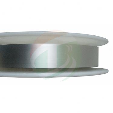
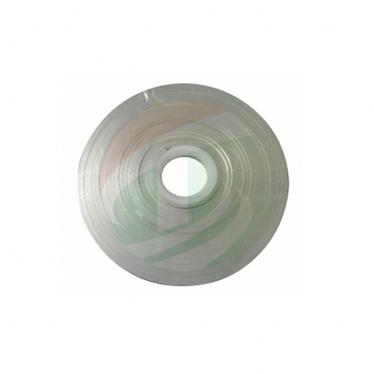
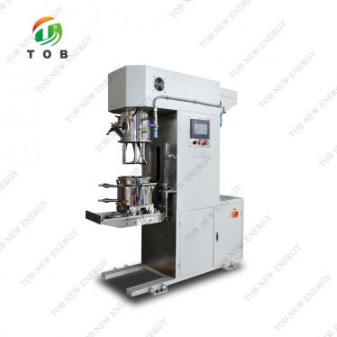
Lithium-metal-on-copper composite foil (Li-Cu foil) is a pre‑fabricated anode current collector that integrates a thin, uniform lithium metal layer directly onto standard battery‑grade copper foil through a controlled lamination (composite welding) process. The TOB‑Li‑Cu‑Foil provides battery manufacturers with a ready‑to‑use anode substrate that eliminates the need for in‑situ electrochemical lithium plating or the manual handling of freestanding lithium foil—both of which introduce significant process variability and safety risks.
This composite foil is engineered specifically for next‑generation battery technologies where lithium metal serves as the active anode material rather than an intercalation host. In a conventional lithium‑ion cell with a graphite anode, the copper current collector simply carries electrons; lithium is stored inside the graphite particles and plates onto the copper only under abuse conditions. By contrast, in a lithium‑metal or anode‑free solid‑state cell, the metallic lithium layer itself constitutes the anode, and the copper foil must serve both as the current collector and as a mechanically stable, chemically inert substrate that forms a clean interface with the lithium. TOB‑Li‑Cu‑Foil addresses both requirements by delivering a flat, oxide‑free lithium surface tightly bonded to the copper, ready for direct stacking or winding with the solid electrolyte and cathode layers.
Ideal for:
- Solid‑state battery developers working on lithium‑metal anodes with oxide, sulfide, or polymer electrolytes.
- “Anode‑free” (lithium‑free) cell research where the initial lithium inventory is provided by a sacrificial lithium layer on the copper current collector.
- Pilot lines building multi‑layer pouch or prismatic solid‑state cells that require precise, consistent lithium loading layer‑by‑layer.
- Academic groups investigating lithium dendrite growth, interfacial resistance, and coulombic efficiency of lithium‑metal electrodes under defined conditions.
- Any team that has previously attempted to handle thin lithium foil manually and encountered tearing, oxidation, or uneven adhesion to the current collector.
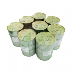
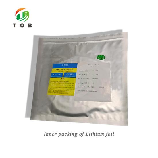
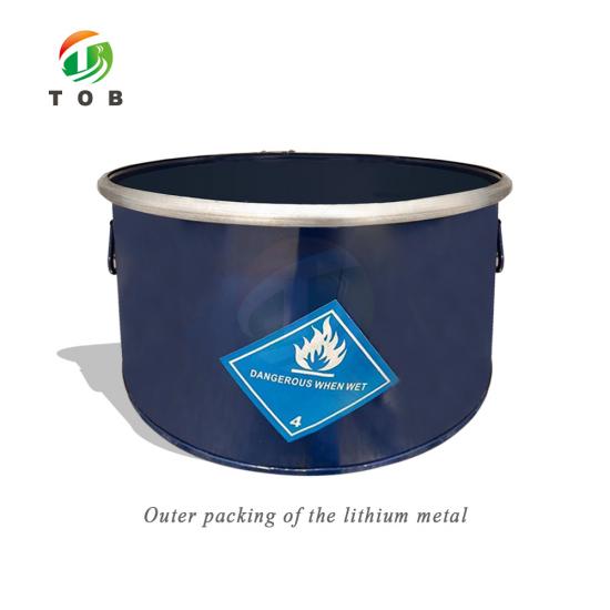
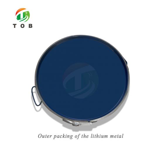
Important Notice: Lithium metal is classified as a dangerous good (Class 9 hazardous material). The product is shipped in sealed argon‑filled aluminised polyester pouches inside steel drums. To ensure accurate quotation and compliant shipping, please specify the required lithium thickness, copper thickness, foil width, and your receiving address when requesting a quotation.
|
|
|


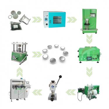
Where Lithium-Copper Composite Foil Fits in Battery Cell Manufacturing
The TOB‑Li‑Cu‑Foil enters the battery production flow during the electrode preparation stage, but unlike conventional cathode coatings or graphite anodes, it arrives as a finished anode current collector that requires no additional slurry coating, drying, or calendaring. The manufacturing sequence for a solid‑state or lithium‑metal cell using this product is:
- Cathode preparation: Cathode active material (e.g., NMC, LFP) is mixed, coated onto aluminium foil, dried, and calendared in the usual manner.
- Solid electrolyte layer preparation: The solid electrolyte (e.g., LLZO pellet, sulfide membrane, polymer‑electrolyte film) is prepared separately.
- Cell stacking: The cathode layer, solid electrolyte layer, and the TOB‑Li‑Cu‑Foil (as the anode) are stacked or wound together in the desired configuration. Because the lithium is already firmly bonded to the copper, there is no need to place a separate lithium foil or to electrochemically plate lithium during the first charge.
- Packaging: The assembled cell stack is sealed in a pouch or prismatic can, and terminal tabs are welded to the copper foil tabs of the anode.
This product is particularly critical for two scenarios:
- Anode‑free solid‑state batteries: The cell is assembled without any lithium metal; lithium is plated in situ from the cathode during the first charge. However, the uniform plating depends on a perfectly clean, uniform copper current collector surface. The TOB‑Li‑Cu‑Foil's smooth lithium layer ensures that the initial lithium inventory is evenly distributed, improving the plating morphology and extending cycle life.
- Multi‑layer pouch cells with thin lithium layers: Manufacturing a 20‑µm thick freestanding lithium foil and then laminating it onto copper without wrinkling or contamination is extremely difficult to do manually. The TOB‑Li‑Cu‑Foil provides this exact structure as a pre‑laminated product, ensuring that every layer in the cell stack has the same lithium loading.
Material Properties and Engineering Characteristics
The performance of a lithium‑metal anode is extremely sensitive to the purity, flatness, and surface cleanliness of the lithium layer. Impurities such as sodium, potassium, or nitrogen compounds can catalyse localised lithium dissolution and promote dendritic growth, leading to short circuits. The TOB‑Li‑Cu‑Foil is produced under strict quality control with material specifications designed to minimise these failure modes.
Chemical Purity (Li Content ≥ 99.9 %)
The lithium metal strip used in the composite foil meets a purity specification of 99.9 % minimum lithium content, with tightly controlled limits on impurity elements known to affect battery performance:
| Element | Li | Na | K | Ca | Fe | N | Si | Cl | Al | Ni | Cu | Mg |
|---|---|---|---|---|---|---|---|---|---|---|---|---|
| Content (wt%, max) | 99.9 (min) | 0.02 | 0.005 | 0.02 | 0.005 | 0.02 | 0.008 | 0.006 | 0.005 | 0.003 | 0.004 | 0.01 |
- Sodium (Na) and Potassium (K): These alkali metals are electrochemically similar to lithium but form lower‑melting‑point phases that can accelerate local dendrite growth. Limiting Na to 0.02 % and K to 0.005 % ensures that the lithium plating and stripping behaviour remains uniform.
- Nitrogen (N): Nitrogen reacts with lithium to form Li₃N, a solid‑electrolyte interphase component with moderate ionic conductivity. However, excessive Li₃N can create a non‑uniform surface film that blocks lithium‑ion transport at the electrolyte interface. The N content is capped at 0.02 %.
- Iron (Fe), Aluminium (Al), and Nickel (Ni): These metallic impurities can form inert particles on the lithium surface that act as local current concentration points, accelerating uneven dissolution. Their combined content is kept at very low levels (Fe ≤ 0.005 %, Al ≤ 0.005 %, Ni ≤ 0.003 %).
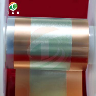
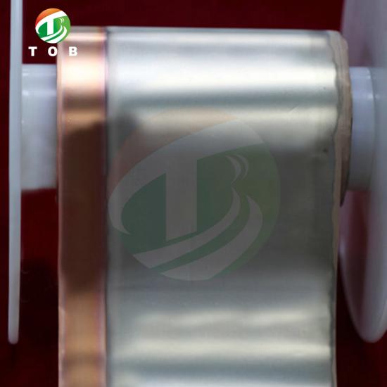
Surface Quality and Appearance
The lithium surface is specified as:
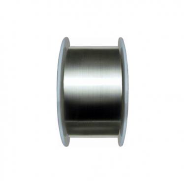
- Flat, bright, and uniformly silver‑colored, with no oil spots, perforations, or tears.
- Free of visible oxides (white patches) and nitrides (yellowish or blue‑grey discolouration). Oxidation occurs instantly if the foil is exposed to ambient air; visible oxide indicates a compromised package or improper handling.
- No wrinkles, holes, cracks, creases, or pressing lines. A wrinkle in the lithium layer creates a local thickness variation that changes the current‑density distribution and promotes uneven lithium stripping during discharge.
- Edges are neat, without cracks. Delamination between the lithium and copper layers is not permitted, as any separation creates a region of high interfacial resistance.
- No inclusions (foreign particles embedded in the lithium), which would block lithium‑ion diffusion and act as dendrite nucleation sites.
Copper Substrate Quality
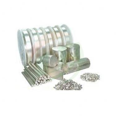
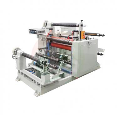
The copper foil (0.010 mm thick, 100 mm wide for the standard configuration) is standard battery‑grade rolled or electrodeposited copper, providing a conductive, flexible support that is compatible with both conventional tab welding and solid‑state cell stacking processes. The lithium is attached by composite welding (a cold‑lamination process) that avoids melting either metal and maintains the original microstructure of both layers.
Product Configurations and Available Specifications
The TOB‑Li‑Cu‑Foil is available in two standard configurations. Custom dimensions can be quoted upon request.
Configuration A: Single‑Side Lithium Coated
| Parameter | Specification |
|---|---|
| Lithium foil thickness | 0.021 mm |
| Copper foil thickness | 0.010 mm |
| Total composite thickness (Li + Cu) | 0.031 mm |
| Lithium foil width | 80.09 mm |
| Copper foil width | 100.00 mm |
| Left margin (Li edge to Cu left edge) | 10.0 ± 1.0 mm |
| Right margin (Li edge to Cu right edge) | 10.0 ± 1.0 mm |
In this configuration, the lithium layer covers the central 80 mm of the 100‑mm‑wide copper foil, leaving an uncoated margin of approximately 10 mm on each side. This margin serves as the electrode tab area for welding: the bare copper can be directly ultrasonically welded to a nickel or copper tab without the lithium interfering with the weld, and without exposing the lithium to the high heat of resistance welding.
Configuration B: Double‑Side Lithium Coated
| Parameter | Specification |
|---|---|
| Top lithium foil thickness | 0.021–0.022 mm |
| Copper foil thickness | 0.010 mm |
| Bottom lithium foil thickness | 0.021–0.022 mm |
| Total composite thickness (Li + Cu + Li) | 0.053–0.054 mm |
| Lithium foil width (both sides) | 80.11 mm |
| Copper foil width | 100.00 mm |
| Left margin (Li edge to Cu left edge) | 10.0 ± 1.0 mm |
| Right margin (Li edge to Cu right edge) | 10.0 ± 1.0 mm |
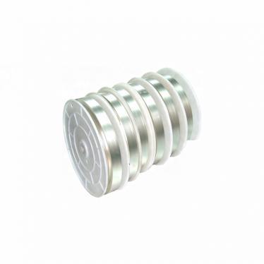
Double‑side coating places lithium on both faces of the copper foil, enabling a higher total lithium inventory per unit area while maintaining the same copper current‑collector thickness. This configuration is used in cells that require excess lithium to compensate for first‑cycle lithium loss or to extend cycle life, or in bipolar cell designs where both faces of the copper foil must serve as anode current collectors.
Key Engineering Advantages of Using Pre‑Laminated Li‑Cu Foil
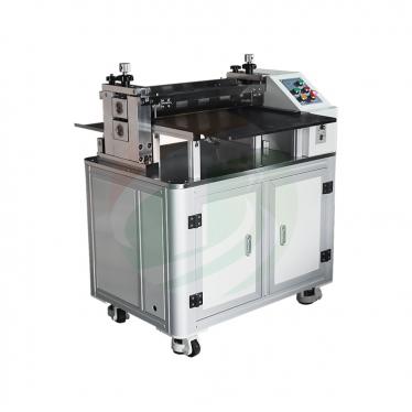
- Eliminates Free‑Standing Lithium Handling Free‑standing lithium foils thinner than 50 µm are extremely difficult to manipulate. They adhere to tools, tear under their own weight, and oxidise within seconds when exposed to ambient moisture and oxygen. By having the lithium pre‑laminated onto copper foil, the assembly gains mechanical stiffness and can be cut to size with standard electrode cutting tools. The 10 mm bare copper margins provide a safe gripping edge for pick‑and‑place automation or manual tweezers during cell assembly.
- Defined, Uniform Lithium Thickness The lithium is rolled or laminated to a controlled thickness of 0.021–0.022 mm, corresponding to an areal capacity of approximately 4.3 mAh/cm² (based on the theoretical capacity of lithium, 3860 mAh/g, and density 0.534 g/cm³). This uniformity is essential for balancing the anode capacity with the cathode loading. Hand‑cut lithium pieces vary in thickness by ±10 % or more, leading to mismatched capacity ratios and accelerated degradation.
- Clean Lithium–Copper Interface The composite welding process creates intimate contact between the lithium and copper at the atomic level, with no intermediate adhesive, conductive paste, or oxide layer. This direct interface maintains the low electrical resistance necessary for uniform current distribution during high‑rate discharge. In a manually assembled stack where a separate lithium foil is simply pressed against a copper current collector, microscopic gaps can form that increase overpotential and promote dendritic growth.
- Dry‑Room Ready and Contamination‑Controlled The entire production and packaging process is conducted in a drying room with strict humidity control. After lamination, the foil is wound on a reel, sealed in an aluminised polyester pouch that has been pre‑dried for over 24 hours, and backfilled with 99.999 % dry argon. The outer packaging is a robust steel drum. This multi‑layer packaging ensures that the lithium arrives at the customer's facility with its original bright, oxide‑free surface, even after international air or sea freight.
- Compatible with Ultrasonic Tab Welding The 10 mm copper margins on both edges allow the foil to be welded using standard ultrasonic or resistance tab welding equipment without any risk of melting or igniting the lithium. The weld is made directly onto the bare copper, which is both safer and more conductive than attempting to weld through the lithium layer. This design consideration directly addresses a common pain point reported by battery engineers transitioning from graphite anodes to lithium‑metal anodes.
- Reduces First‑Cycle Lithium Loss Compensation Complexity In anode‑free or lithium‑limited cells, cell designers often add a sacrificial lithium layer onto the copper current collector to compensate for lithium consumed during SEI formation. The TOB‑Li‑Cu‑Foil provides this lithium in a pre‑measured, uniform form that is easy to integrate into cell stacks, removing the need for unreliable in‑situ electrochemical pre‑lithiation steps that add process complexity, cost, and variability.
Comparison: TOB‑Li‑Cu‑Foil vs. Manual Lithium Foil Assembly
| Feature | TOB‑Li‑Cu‑Foil | Manual Assembly (separate Li foil + Cu foil) |
|---|---|---|
| Lithium thickness uniformity | ± 1 µm across the roll (controlled lamination process) | ± 5 µm typical (hand‑cut) |
| Lithium–copper interface | Direct composite weld, no adhesive, R < 0.1 Ω·cm² | Pressed contact only, variable resistance (can be > 10 Ω·cm² initially) |
| Oxide and contamination control | Produced and packed under dry argon, sealed in pre‑dried pouches | Exposed to glovebox atmosphere during assembly; oxide formation depends on operator skill and glovebox H₂O/O₂ levels |
| Mechanical robustness | Copper backing provides stiffness; foil can be cut with precision dies | Free‑standing Li foil is fragile; tears during cutting, transfer, and stacking |
| Tab welding | Bare copper margins for safe, standard ultrasonic welding | Must weld to copper or nickel tab through Li or use complex clamping methods |
| Process repeatability | Every layer identical; suitable for automated stacking | High variability; unsuited for scaling beyond a few lab cells |
| Time to assemble a 10‑layer cell stack | Under 15 minutes (cut, stack, weld) | Over 1 hour (cut each lithium piece, position, press, verify) |
Why solid‑state battery groups standardise on pre‑laminated Li‑Cu foil: Research groups that initially assemble cells by manually placing lithium foil onto copper current collectors report two recurring problems. First, the cycle life data shows large scatter because the lithium‑copper contact varies from cell to cell. Second, as the number of layers in the stack increases (e.g., 5‑layer to 20‑layer pouch cells), the assembly yield drops sharply because one torn lithium piece ruins the entire stack. Pre‑laminated foil removes both sources of variation, allowing the group to focus on the solid electrolyte and cathode chemistry rather than on anode preparation.
Handling, Storage, and Safety Guidelines
Lithium metal reacts exothermically with water, moisture, oxygen, and nitrogen. Proper handling procedures are non‑negotiable for both safety and material quality.
Storage and Unpacking
- As‑received storage: Store the sealed steel drum in a rainproof, clean, dry, non‑corrosive, and well‑ventilated environment. Do not store outdoors. The storage area must be free of water sources and must have appropriate fire‑fighting equipment for metal fires (Class D extinguisher).
- Opening the drum: Open only in a dry room or glovebox with a dew point ≤ –40 °C and oxygen level < 10 ppm. Once the steel drum is opened, the aluminised polyester pouch inside must remain sealed until transferred into the glovebox antechamber.
- Pouch opening: Open the argon‑filled pouch only inside the glovebox. Cut the pouch with ceramic‑bladed scissors or tear carefully along the seal. Do not use metal blades that could spark.
- Partial use: If the entire roll is not consumed in one session, re‑seal the remaining foil inside the aluminised pouch with a heat sealer while still inside the glovebox, backfill with dry argon if possible, and place back in the steel drum.

Working with the Foil
- Cutting: Use a precision die cutter or a ceramic tool. The copper backing provides excellent dimensional stability; standard electrode cutting dies designed for copper foil (e.g., Ø14 mm for coin cells) work well.
- Glove selection: Wear clean, powder‑free nitrile gloves inside the glovebox gloves. Oils or moisture from the skin transferred to the foil will appear as dark spots after several days even inside the glovebox.
- Welding tabs: Weld tabs only onto the bare copper margin. Use ultrasonic welding or resistance welding with the parameters validated on plain copper foil of the same thickness. Never weld directly on the lithium‑coated area.
- Waste disposal: All offcuts and used lithium foil must be disposed of as reactive metal waste. Place material in a sealed container and contact a licensed hazardous waste disposal service. Do not dispose of lithium‑containing waste with regular laboratory or battery waste.
Transport
During transportation, the product must be protected from fire sources and moisture. Avoid violent collisions; do not roll the steel drums on the ground. The packaging is UN‑certified for lithium metal; ensure that shipping documentation accurately declares the product per the applicable dangerous goods regulations (ADR, IATA, IMDG).

Engineering FAQ — Lithium-Copper Composite Foil for Battery Research and Production
Q1: What is the areal capacity of the 0.021 mm lithium layer, and how do I calculate the required cathode loading to match it? The areal capacity of a lithium metal layer is calculated from its thickness, density, and specific capacity:
- Thickness: 0.021 mm = 21 µm
- Density of lithium: 0.534 g/cm³
- Specific capacity: 3860 mAh/g
- Areal capacity = (21 × 10⁻⁴ cm) × (0.534 g/cm³) × (3860 mAh/g) ≈ 4.3 mAh/cm²
If your cathode loading is, for example, 2 mAh/cm², then a single side of 0.021 mm lithium provides an excess of over 2× relative to the cathode. This excess is required to compensate for first‑cycle lithium loss to SEI formation and to ensure lithium is available for extended cycling. The exact ratio depends on your electrolyte chemistry; a good starting point is an N/P (anode/cathode capacity ratio) of 2.0–2.5 for lithium‑metal cells with liquid or solid electrolytes.
Q2: Can this foil be used with sulfide solid electrolytes, given that lithium reacts with sulfur? Yes—but only if a protective interlayer (e.g., LiPON, Al₂O₃, or a polymer buffer) is deposited between the lithium and the sulfide electrolyte. The pristine, oxide‑free surface of the TOB‑Li‑Cu‑Foil provides an ideal substrate for vacuum‑depositing such interlayers because there is no native oxide to interfere with adhesion. Many groups sputter a thin LiPON or gold interlayer onto the lithium surface before contacting the sulfide electrolyte. The copper backing also facilitates handling of the foil during the interlayer deposition process.
Q3: How long can the foil stay inside the glovebox after opening the pouch before it degrades? Under a glovebox atmosphere of H₂O < 0.1 ppm, O₂ < 0.1 ppm, and an inert argon environment, the lithium surface will remain bright and oxide‑free for at least 48 hours. After this time, trace reactions with residual impurities in the glovebox atmosphere may produce a faint darkening, which is usually a sub‑nanometer Li₂O layer that does not significantly affect initial interfacial resistance. However, for critical experiments (e.g., measuring interfacial resistance by EIS), we recommend using the foil within the first 24 hours of opening. If you observe a colour change to dark grey or black, the foil has been exposed to moisture and should be discarded.
Q4: Is the copper foil surface treated or coated in any way before lithium lamination? No. The copper foil is used in its standard battery‑grade condition, without any anti‑tarnish coating or passivation layer. Any coating would interfere with the lithium adhesion and increase the electrical resistance at the interface. The composite welding process itself is performed under dry conditions that prevent oxide formation, so the copper surface remains clean at the point of bonding. If your specific cell chemistry requires a protective coating (e.g., a carbon interlayer to suppress lithium dendrites), this can be applied to the bare copper foil prior to lamination—contact TOB with your specification for custom quoting.
Q5: Can the foil be cut into circles for coin‑cell assembly without causing delamination at the edges? Yes. When using a sharp, properly aligned punch die, the copper‑lithium composite cuts cleanly without delamination at the cut edge. The cold‑welding bond between lithium and copper is mechanically robust. However, avoid using a blunt die or a scissor‑type cutter that applies shear in a narrow zone—this can smear the lithium and locally separate it from the copper. A rotary punch with a clearance of ≤ 2 % of the foil thickness produces the best edge quality. The resulting discs are suitable for both coin‑cell and Swagelok‑type cell testing.
Start building solid‑state or lithium‑metal cells with consistent, ready‑to‑stack anodes. Request a quotation for the TOB‑Li‑Cu‑Foil in your required dimensions, or contact our materials engineers to discuss custom thicknesses, widths, and single‑ vs. double‑side configurations.
tob.amy@tobmachine.com | +86 181 2071 5609
If you are interested in our products and want to know more details,please leave a message here,we will reply you as soon as we can.