
- Home
- >
Battery Materials
- >
Sodium-ion Battery Materials
- >
Sodium-ion Battery Layered Oxide Cathode Materials
Categories
Hot Products
Loading...
Sodium-ion Battery Layered Oxide Cathode Materials
Brand:
TOB NEW ENERGYitem no.:
TOB-NA-C-01order(moq):
1Payment:
L/C,Tproduct origin:
Chinashipping port:
XIAMEN
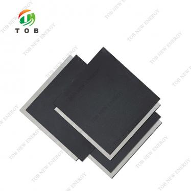
TOB-NA-C-01 Layered Oxide Cathode Material for High-Performance Sodium-Ion Batteries
1. Product Overview and Ideal Applications
Sodium-ion batteries (SIBs) are rapidly emerging as a sustainable and cost‑effective alternative to lithium‑ion technology, particularly for large‑scale stationary energy storage systems where raw‑material cost and supply‑chain security matter most. The TOB‑NA‑C‑01 is a layered oxide cathode material specifically engineered for sodium‑ion cells, combining high specific capacity, excellent first‑cycle coulombic efficiency, and robust particle morphology that withstands the mechanical stresses of electrode calendaring.
Unlike many lithium cathode materials that rely on expensive cobalt, TOB‑NA‑C‑01 is based on abundant transition‑metal elements, aligning directly with the core motivation for sodium‑ion technology: a scalable, lower‑cost chemistry without compromising performance. The powder delivers a reversible gram‑capacity of 135.61 mAh/g with an initial coulombic efficiency of 93.01 %, meaning that very little of the first‑cycle sodium inventory is irreversibly trapped in the solid‑electrolyte interphase. Its particle size distribution—D50 of 11.55 µm—is optimised for electrode fabrication, providing good tap density and calendaring behaviour while still offering sufficient surface area for charge transfer.
Ideal for:
- Battery manufacturers and R&D groups developing cylindrical, pouch, or prismatic sodium‑ion cells for grid storage, low‑speed electric vehicles, and backup power.
- Researchers formulating and benchmarking sodium‑ion cathode materials in half‑cell and full‑cell configurations.
- Pilot lines seeking a consistent, well‑characterised sodium‑ion cathode powder to validate electrode coating and cell assembly processes before scaling to larger production volumes.
- Any team that has tried lower‑grade sodium cathode materials and encountered severe capacity fade due to particle cracking or excessive side reactions with the electrolyte.

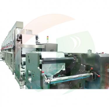
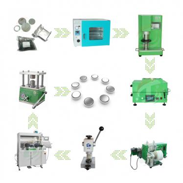
2. Where This Cathode Material Fits in Sodium‑Ion Cell Manufacturing
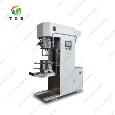
Sodium‑ion cell production follows a process chain very similar to that of lithium‑ion batteries. The TOB‑NA‑C‑01 enters the workflow at the electrode preparation stage: the powder is mixed with a conductive additive (such as carbon black or carbon nanotubes) and a polymeric binder (typically PVDF in NMP, or water‑based binders for more sustainable processing), and the resulting slurry is coated onto aluminium foil. After drying and calendaring, the cathode sheet is combined with an anode (usually hard carbon) and a sodium‑salt electrolyte to form the complete cell.
The manufacturing sequence is:
- Slurry mixing: The cathode powder is blended with conductive carbon and binder.
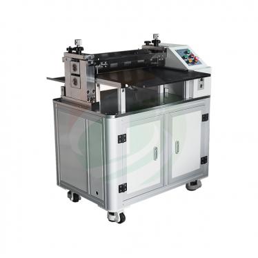
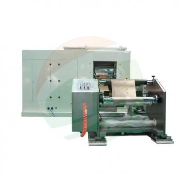
- Coating: The slurry is applied to aluminium foil using a doctor blade or slot‑die coater.
- Drying and calendaring: The electrode is dried and then pressed to a target density.
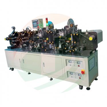
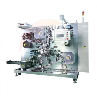
- Cell assembly: The cathode, separator, and anode are stacked or wound together, placed in a cell housing, and filled with electrolyte.
- Formation: The cell undergoes the first charge‑discharge cycle to activate the electrodes and form the SEI.
Because sodium ions are larger than lithium ions, the cathode material must accommodate significant volume changes during cycling without particle fracture. The TOB‑NA‑C‑01’s particle morphology and high compaction density are designed with this requirement in mind.
Process optimisation best practices (derived from sodium‑ion battery research):
- Moisture control: Although the moisture content is low (138.99 ppm as supplied), sodium‑based cathode materials can be hygroscopic. Always pre‑bake the powder at 120–150 °C for 6–8 hours under vacuum or dry inert gas before slurry making. Store opened bags in a dry room or glovebox (<1 % RH).
- Slurry pH management: The powder has a measured pH of 12.3 when dispersed in water, indicating the presence of residual alkaline surface species (likely sodium carbonate or hydroxide). This can cause PVDF dehydrofluorination in NMP. To mitigate this, add a small amount of anhydrous acid (e.g., oxalic acid) to the NMP/PVDF solution before powder addition, or switch to an acid‑tolerant binder such as PAA (polyacrylic acid) for aqueous processing.
- Calendaring density: With a solid density of 2.11 g/cm³, the powder can be pressed to a reasonably high electrode density without particle cracking. Start with a target of 2.6–2.8 g/cm³ electrode density (typical for layered oxides) and adjust based on your cell design.
- Electrolyte pairing: The standard sodium‑ion electrolyte is 1 M NaPF₆ in EC:DMC (1:1) or EC:PC. Some formulations with fluoroethylene carbonate (FEC) additive can improve cycling stability by forming a more robust cathode‑electrolyte interphase. The high first‑cycle efficiency of 93 % indicates that the material does not consume excessive electrolyte during formation, which is an advantage.
3. Material Properties and Electrochemical Characteristics
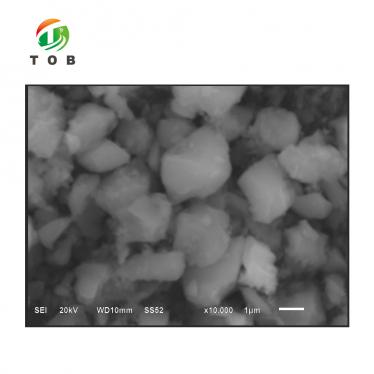
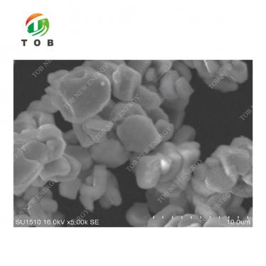
The TOB‑NA‑C‑01 belongs to the O3‑type layered oxide family, where sodium ions occupy octahedral sites between transition‑metal oxide slabs. This structure enables reversible sodium intercalation with a theoretical capacity that can exceed 150 mAh/g, depending on the precise transition‑metal composition. The measured gram capacity of 135.61 mAh/g indicates that a significant portion of the theoretical capacity is accessible at practical charge‑discharge rates, while the 93.01 % initial coulombic efficiency shows that most of the extracted sodium is successfully re‑inserted during the first cycle.
Particle size distribution and electrode processing
The particle size parameters—D10 5.89 µm, D50 11.55 µm, D90 20.43 µm, D99 28.53 µm—describe a moderate, slightly broad distribution. A D50 of 11.55 µm is well within the range typically used for industrial battery electrodes: small enough to ensure reasonable lithium‑ion (or sodium‑ion) diffusion distances, yet large enough to provide high tap density and avoid excessive specific surface area. The relatively low specific surface area of 0.24 m²/g is beneficial because it limits the extent of side reactions between the cathode and the electrolyte, which can consume active sodium and generate resistive surface films that increase impedance over time.
Structural stability and compaction
The solid (true) density of 2.11 g/cm³ is typical for layered oxide materials. When compounded into an electrode and calendared, this translates to a practical electrode density that supports high volumetric energy density—a key requirement for commercial cells. Unlike some sodium cathode materials that suffer from cracking during calendaring, TOB‑NA‑C‑01 is designed to withstand the compaction forces required to reach an electrode density of 2.6–2.8 g/cm³ without compromising particle integrity, which helps maintain long cycling stability.
Surface chemistry and moisture
The pH value of 12.3 (measured by dispersing the powder in distilled water) reflects the presence of surface alkaline residues. This is common for layered oxides synthesized via co‑precipitation and calcination routes, where a slight excess of sodium precursor is used. While the moisture content is a low 138.99 ppm, the alkaline surface can absorb CO₂ from the air to form sodium carbonate, which can later decompose during cycling and produce gas. Proper storage in sealed, moisture‑free packaging and prompt use after opening are recommended to minimise such effects. Pre‑baking the powder as described further reduces these surface species.
4. Complete Material Specifications
The following technical parameters are measured for every production batch of TOB‑NA‑C‑01 and are guaranteed to fall within the stated ranges.
|
Item |
Result |
|
|
Particle size |
D10(µm) |
5.89 |
|
D50(µm) |
11.55 |
|
|
D90(µm) |
20.43 |
|
|
D99(µm) |
28.53 |
|
|
Specific surface area(m2/g) |
0.24 |
|
|
PH |
12.30 |
|
|
Solid density(g/cm3) |
2.11 |
|
|
Moisture( PPM) |
138.99 |
|
|
Initial Coulombic Efficiency(%) |
93.01 |
|
|
Gram capacity(mAh/g) |
135.61 |
|
Note: The values represent a typical batch. Minor variations within acceptable tolerances may occur. For the most recent lot‑specific data, request the Certificate of Analysis.
5. Key Engineering Advantages of TOB‑NA‑C‑01 for Sodium‑Ion Batteries
(1) High Specific Capacity — 135.61 mAh/g
In a sodium‑ion full cell against a hard‑carbon anode, this capacity translates to a cathode‑limited specific energy that can approach 150 Wh/kg at the cell level, making it competitive with commercial LFP lithium‑ion cells for stationary storage. The capacity is stable over hundreds of cycles when paired with an appropriate electrolyte.
(2) Excellent First‑Cycle Efficiency — 93.01 %
Sodium‑ion cells often suffer from large irreversible capacity losses due to SEI formation on the anode and side reactions on the cathode. An efficiency above 93 % means that the cathode itself does not contribute significantly to these losses, preserving more of the expensive sodium inventory for useful cycling. This reduces the need for cathode over‑sizing and improves overall energy density.
(3) Optimized Particle Morphology for Electrode Fabrication
With a D50 of 11.55 µm and a low specific surface area (0.24 m²/g), the powder flows well during mixing and coating, achieves high packing density, and minimises electrolyte‑cathode side reactions. The narrow spread between D10 and D90 ensures consistent coating weight across the electrode, which is essential for uniform current distribution and long cycle life.
(4) High Solid Density — 2.11 g/cm³
This facilitates electrode calendaring to a high volumetric density without particle breakage. In large‑format cells, a higher electrode density directly increases the energy stored per unit volume, reducing system cost.
(5) Low Moisture Content — 138.99 ppm
Handling moisture‑sensitive sodium materials is often challenging. The low as‑received moisture minimises the risk of slurry gelling due to binder hydrolysis and reduces the formation of hydrofluoric acid if NaPF₆‑based electrolytes are used. It also indicates that the powder has been dried and packaged under controlled conditions.
(6) Consistent Batch‑to‑Batch Quality
TOB’s quality management system ensures that every lot of TOB‑NA‑C‑01 is subjected to the same rigorous testing protocol—particle size analysis, pH, moisture, and electrochemical performance. This consistency allows cell manufacturers to scale their processes with confidence, without the need to re‑qualify material for each new batch.
6. Comparison: TOB‑NA‑C‑01 vs. Generic Sodium Layered Oxide Cathode Powders
| Feature | TOB‑NA‑C‑01 | Typical Generic Layered Oxide for SIBs |
| Gram capacity | 135.61 mAh/g | Often 120–130 mAh/g |
| Initial coulombic efficiency | 93.01% | Typically 85–90 % |
| Particle size (D50) | 11.55 µm | Varies widely, often >15 µm or <5 µm |
| Specific surface area | 0.24 m²/g | Can be 0.5–1.5 m²/g, leading to more side reactions |
| Moisture (as‑received) | 138.99 ppm | Often >300 ppm |
| Solid density | 2.11 g/cm³ | May be lower, affecting electrode density |
| Lot‑to‑lot consistency | Controlled, with data sheet | Often inconsistent, minimal documentation |
Why choose TOB‑NA‑C‑01 over lower‑cost alternatives?
Purchasing a sodium cathode powder based solely on price can lead to hidden costs: inconsistent electrochemical performance, lower utilisation of active material, and production yield losses. The TOB‑NA‑C‑01 provides documented, repeatable performance. The high first‑cycle efficiency alone can save several percent of active material cost because less cathode loading is needed to compensate for formation losses. In a 1 MWh grid storage project, that difference translates into a measurable reduction in the total system cost.
7. Common Processing Problems and Practical Mitigation
| Problem | Likely Cause | Recommended Action with TOB‑NA‑C‑01 |
| Slurry gelation or binder instability | Alkaline surface (pH 12.3) reacting with PVDF. | Add a small amount of acid to the solvent before binder addition, or use a non‑fluorinated binder (PAA, CMC/SBR). Pre‑baking the powder reduces surface alkalinity. |
| Low electrode density after calendaring | Insufficient calendaring force or unsuitable particle morphology. | The solid density of 2.11 g/cm³ indicates good innate tap density. Increase calendaring line pressure in stages, and ensure the powder is well‑dispersed. Target 2.6–2.8 g/cm³ electrode density. |
| Capacity fading faster than expected | Moisture or surface impurities causing electrolyte decomposition. | Bake powder before use to reduce moisture. Store opened bag in dry conditions. Use an electrolyte with FEC additive to stabilise the cathode‑electrolyte interface. |
| Coating inhomogeneity | Agglomerates or broad particle size distribution. | Dry‑blend with carbon black before adding solvent to break soft agglomerates. The moderate D50 and low surface area help avoid hard agglomerates. |
| Gas generation during cycling | Residual carbonate species on the particle surface decomposing. | Pre‑baking reduces surface carbonates. Additionally, use a formation protocol with a low‑rate initial charge to allow gentle SEI build‑up. |
8. Recommended Electrode Fabrication Parameters (Starting Points)
These parameters are suggested based on typical sodium‑ion cathode formulations and the material characteristics of TOB‑NA‑C‑01. Always optimise for your specific equipment and cell design.
| Parameter | Recommended Value / Range | Notes |
| Cathode composition | TOB‑NA‑C‑01 : Carbon black : PVDF = 92 : 4 : 4 (weight) | Adjust binder and carbon according to desired rate capability. |
| Solvent | NMP (anhydrous) or deionised water for aqueous binders | If using water, add binder first and neutralise with small acid amount. |
| Dry‑blend | Mix powder + carbon for 15 min at 200 rpm | Breaks agglomerates and coats particles with conductive network. |
| Slurry solid content | 45–55 % | Target viscosity 3000–6000 mPa·s for doctor‑blade coating. |
| Coating thickness (wet) | 100–150 µm | Adjust to achieve target areal capacity (e.g., 1.5–2.0 mAh/cm²). |
| Drying profile | Ramp: 80 °C / 30 min, then 120 °C / 30 min under ventilation | Gradual drying prevents skinning and cracking. |
| Calendaring | Target electrode density 2.6–2.8 g/cm³ | Two‑pass calendaring recommended. |
| Electrolyte | 1 M NaPF₆ in EC:DMC (1:1) + 2 % FEC | Optional additive: 1 % VC. |
| Counter electrode (full cell) | Hard carbon anode, pre‑sodiated if necessary | N/P ratio 1.1–1.2. |
9. Engineering FAQ — Sodium‑Ion Layered Oxide Cathode Material
Q1: Can TOB‑NA‑C‑01 be used with aqueous binders to avoid NMP?
Yes, but attention must be paid to the surface pH. The powder’s inherent alkalinity (pH 12.3) may cause corrosion of the aluminium current collector in an aqueous environment. To mitigate this, add a buffer (such as a small amount of phosphoric acid or carbonic acid) to the aqueous binder solution before powder addition, or coat the aluminium foil with a thin protective carbon layer. Polyacrylic acid (PAA) binder is more tolerant of alkaline powders than CMC alone and can contribute to good adhesion.
Q2: What is the typical voltage range for testing this material, and what specific capacity can be expected?
The material is typically tested between 2.0 V and 4.0 V versus Na⁺/Na. In a half‑cell, at a rate of 0.1C, the first discharge capacity reaches the specified 135.61 mAh/g. The operating voltage is relatively high, which is advantageous for energy density. At higher rates (1C), the capacity retention is typically >80 % of the low‑rate value, though this depends on electrode formulation.
Q3: How should I store the powder if I only use part of a bag for my experiment?
After opening, immediately transfer the remaining powder to a container that can be tightly sealed, preferably under argon or dry nitrogen. Place it in a dry room or glovebox with a dew point lower than –40 °C. Avoid storage in ambient air; the alkaline surface will absorb CO₂ and moisture within hours, forming surface carbonates that degrade electrochemical performance. If you must store outside a glovebox, double‑bag the container with desiccant packs.
Q4: The pH value of 12.3 seems high. Will this affect the cycling performance negatively?
The pH value is measured by the distilled water method, which neutralises surface alkaline species. A pH in this range is not unusual for sodium layered oxide materials and mainly reflects the presence of residual sodium carbonate/hydroxide from synthesis. While these species can cause some side reactions if left untreated, the typical pre‑baking step (120–150 °C under vacuum) and the use of a suitable electrolyte additive largely mitigate these effects. The high initial coulombic efficiency of 93.01 % is evidence that the surface species are manageable.
Q5: Can this material be mixed with other cathode powders to fine‑tune cell performance?
Yes, it is physically and chemically compatible with other layered oxides and even polyanionic materials (such as Na₃V₂(PO₄)₃). Blending is sometimes done to combine the high capacity of layered oxides with the structural stability of polyanionic compounds. If blending, ensure that the particle sizes are similar to avoid segregation during coating. Our engineers can advise on blending strategies based on your target performance metrics.
Ready to test the next generation of sodium‑ion cathode materials in your own cells? Request the full Certificate of Analysis for the latest batch, or contact our sodium‑ion battery team to discuss electrode recipes and cell design for your specific application.
tob.amy@tobmachine.com | +86 181 2071 5609
You May Also Need
- TOB-NA-A-01 Irregular Hard Carbon Sodium-ion Battery Anode Materials — The ideal anode counterpart for your sodium-ion full cell, offering high capacity and excellent cycling stability against layered oxide cathodes.
- TOB-PBAs Prussian Blue Powder for Sodium-ion Battery Cathode Materials — An open‑framework cathode material with fast sodium‑ion diffusion and low‑cost synthesis, suitable for grid‑storage applications.
- TOB-PW Prussian White Powder as Sodium Ion Active Material — High‑sodium‑content cathode powder for enhanced energy density in sodium‑ion cells, with excellent structural stability.
- TOB-NVP Carbon-Coated Sodium Vanadium Phosphate Powder for Sodium Ion Battery Cathode — NASICON‑type cathode material with exceptional rate capability and ultra‑long cycle life, ideal for high‑power sodium‑ion batteries.
Previous:
Irregular Hard Carbon Sodium-ion Battery Anode MaterialsNext:
Prussian Blue Powder for Sodium-ion Battery Cathode Materials
If you are interested in our products and want to know more details,please leave a message here,we will reply you as soon as we can.