

Categories
new blog
- Solid-State Battery Manufacturing Equipment Guide 2026–2027
- Supercapacitors vs Batteries: Complementary Industrial Energy Storage
- Battery Electrolyte Selection Guide: What Procurement Managers Must Know
- Coin Cell Lab Equipment: The Complete Checklist for Battery R&D Labs
- Battery Cathode Materials Compared: NMC vs LFP vs NCA
Tags
How to detect the short circuit caused by burrs on battery electrodes?
This article analyzes the causes of zero voltage. Focused on the phenomenon of zero voltage in the battery caused by electrode burrs. By identifying the cause of the short circuit, we aim to precisely resolve the problem and better understand the importance of controlling electrode burrs during production.
Experiment
1. Battery preparation
This experiment uses lithium nickel cobalt manganate material (NCM111) as the positive active material. Mix the positive active material, SP carbon black, PVDF binder, and NMP solvent at a mass ratio of 66:2:2:30 to make a slurry. The slurry is coated on a 15 μm thick carbon-coated aluminum foil, and the coating amount on one side is 270 g/m2. Place the positive electrode in an oven at a temperature of (120±3)°C to dry for 24 hours, and then the calendering process is carried out to make the compacted density of the electrode 3.28g/cm3. The negative active material uses lithium titanate material Li4Ti5O12. Mix the negative active material, SP carbon black conductive agent, PVDF binder and NMP solvent according to the mass ratio of 52:2:2:44 to make a slurry. The anode slurry is coated on a 15 μm thick carbon-coated aluminum foil, and the coating amount on one side is 214 g/m2. Place the negative electrode in an oven at a temperature of (110±3)°C to dry for 24 hours, and then perform a rolling process to make the compacted density of the electrode piece 1.85g/cm3. The dried electrode is cut into pieces with a width of (136.0±1.0) mm, and the electrode burrs should not exceed 12μm. The electrolyte uses 1mol/L LiPF6/EC+EMC+DMC (volume ratio 1:1:1). The separator is a 20 μm thick polyethylene (PE) porous separator. The above materials are assembled into 66160 cells with a design capacity of 45Ah. After winding and assembly, the top cover of the aluminum shell was welded and sealed, and the experimental cells was placed in an oven at a temperature of (85±3)°C to dry for 24 hours.
After drying, filling the battery cells, and the amount of electrolyte is 200g. After electrolyte filling, the cells were left to stand at room temperature for 72 hours. After the standing, all experimental cells were tested for open circuit voltage (OCV), and the internal resistance and voltage of the battery were recorded.
2. Charging test
When performing internal resistance and voltage analysis, use an AC internal resistance tester for testing. Use the 5V-50A high-precision battery performance testing system to test the charging performance of the battery. For cells that have been left standing after filling, when performing a voltage test, first short-circuit the cell to reduce its voltage to 0, which is a zero-voltage cell.
Then perform a charging test on the zero-voltage cell. When the ambient temperature is (25±3)℃, different currents (such as 1A, 2A and 3A) are used for charging. The experiments were conducted in the order of current from small to large and time from short to long. The charging time was set to 5 seconds, 10 seconds and 25 seconds respectively. Observe the changes in battery voltage after each charging time.
3.Self-discharge test
Use a two-dimensional tester for electrode burr analysis. Use an AC internal resistance tester for internal resistance and voltage analysis. Use a 5V-50A high-precision battery performance testing system to test electrical performance. Use a high and low temperature box to control the cells temperature. After the zero-voltage cells before formation is charged, the burr fuses and zero voltage no longer appears. Test the normal formation process of this battery. The formation process is as follows:
①After the temperature of the high temperature box reaches 120℃, wait for 120 minutes.
②Charge with 1.0 times C current to the cut-off voltage of 2.8V, then switch to constant voltage charging. The charging cut-off time is 2 hours.
③Wait for 10 minutes.
④Discharge with 1.0 times C current to the cut-off voltage of 1.5V, and then switch to constant voltage discharge. The discharge cut-off time is 2 hours.
⑤Wait for 10 minutes.
⑥Repeat steps 2 to 5 3 times.
⑦Charge with 1.0 times C current, charging time is 0.7 hours, then charge with 2.3V constant voltage, cut-off current is 0.45A.Conduct self-discharge test on the formed cells. Use the method of testing static voltage and test the voltage for no less than two months. After the cells are left standing at room temperature (25±5)°C for 24 hours, the open circuit voltage is tested and recorded. Subsequently, the cells continued to stand at room temperature for one month and two months, and then the open circuit voltage was tested and recorded again.
Results and discussion
1. Comparison of battery voltage before formation
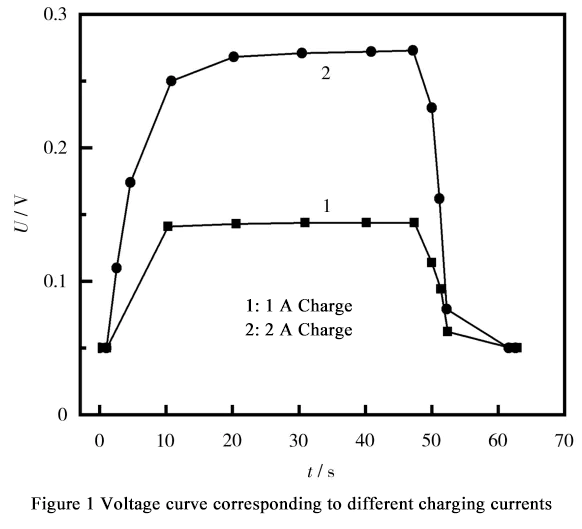
Figure 1 shows the battery voltage changes during 1A and 2A charging and after stopping charging. It can be seen from the figure that a zero-voltage battery can be approximately regarded as a short circuit caused by internal burrs. The battery can withstand a current test of less than 2A within 1 minute. When the charging current is 1A and 2A, due to the short circuit caused by internal burrs, the voltage reaches a stable value and no longer changes. When charging is stopped, the voltage quickly returns to 0.
Continue to increase the charging current, change the charging current to 3A, and set the charging time to 5s, 10s, and 25s respectively. The battery charging test curve is shown in Figure 2.
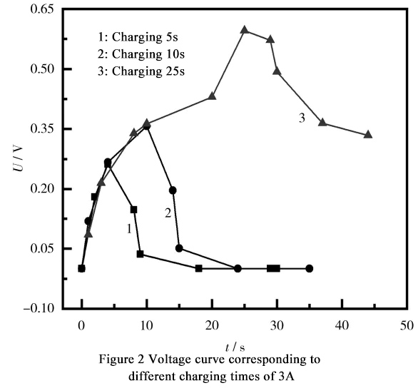
According to the observation in Figure 2, when the charging current reaches 3A, the voltage change of the battery is similar to that of 1A and 2A charging under the charging time of 5 seconds and 10 seconds. As the charging time prolongs, when the charging time exceeds 10 seconds, the voltage slowly rises. When the charging time reaches 20 seconds, the voltage rises rapidly. After charging stops, the voltage drops slowly, and the previous zero voltage phenomenon does not appear in a short period of time.
Based on the speed of voltage change during charging, it can be concluded that the burrs inside the battery have been thermally fused due to the heat generated by charging. Before the burrs fuses, the voltage shows a slowly rising stage within 10 to 20 seconds after charging starts.
After 20 seconds, the burr fuses, and the battery voltage rises rapidly. After stopping charging, the battery voltage slowly decreases. It is worth noting that after the burr fuses, metal impurities still remain inside the battery, causing self-discharge faster than normal batteries. Therefore, after normalizing the battery, it is necessary to test its self-discharge rate.
2. Comparison of battery self-discharge after formation
The battery selected for the experiment was charged and discharged according to the above formation process. After step ⑦, the state of charge (SOC) of the battery was approximately 80%. The self-discharge test of the battery was conducted at room temperature and compared with batteries containing impurities from the same batch. The test data is shown in Table 1.
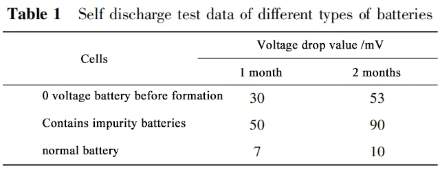
It can be seen from Table 1 that the battery self-discharge caused by burrs does exist and has an impact on the battery's charge retention capability. Analyzing the causes of self-discharge abnormalities through charging current can intuitively reflect the abnormal situation of electrode burrs during the manufacturing process.
This shows that it is necessary to further strengthen process control requirements during the production process and maintain the cutter in a timely manner to ensure battery performance and reduce safety hazards. After the burr is blown, there are still metal impurities inside the electrode.
According to the self-discharge data after measuring the battery capacity, it can be concluded that after a normal battery is left at room temperature for one month, the voltage drops by about 7mV; after two months, the voltage drops by about 10mV. This shows that the self-discharge rate of batteries with excessive burrs is greater than that of normal batteries. Taking into account the voltage before formation and the self-discharge data analysis after capacity division, it can be concluded that excessive burrs will lead to abnormal battery charge retention performance. The burrs present on the battery electrodes will not disappear completely and will affect the performance of the battery in the long term.
In summary, burrs have a negative impact on battery performance, so measures need to be taken to reduce the formation of burrs during the manufacturing process to ensure battery performance and safety.
Conclusion
In the battery manufacturing process, controlling the size of electrode burrs is a key parameter. When a burr causes a short circuit, the voltage of the battery will become 0 after filling. By charging a short-circuited battery caused by a burr with a small current, a stable voltage can be observed. When the current reaches the burrs fuse value, there are still metal impurities inside the battery, which will continue to affect the self-discharge of the battery, resulting in a higher self-discharge rate than normal batteries. This method can be used to identify battery short circuits caused by burrs during battery manufacturing. By observing changes in voltage, we can guide the strengthening of inspections of slitting, die-cutting and winding equipment during the battery production process to avoid the production of large quantities of unqualified batteries. Therefore, by charging short-circuited batteries caused by burrs with low current and monitoring voltage changes, problems in the battery manufacturing process can be effectively identified and relevant process controls can be guided to ensure battery quality and performance.