
- Home
- >
18650 Battery Pack Assembly Equipment
- >
Battery Pack Welding Machine
- >
Double-Side Auto Spot Welder for Battery Pack Assembly
Categories
Hot Products
Loading...
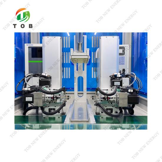
Double-Side Auto Spot Welder for Battery Pack Assembly
Brand:
TOB NEW ENERGYitem no.:
TOB-850DN-XZ-10000Aorder(moq):
1setPayment:
L/C,T/Tproduct origin:
Chinashipping port:
XIAMEN
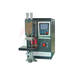
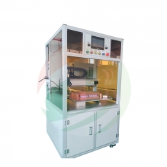
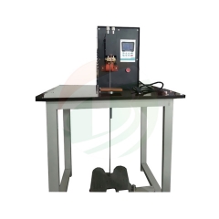
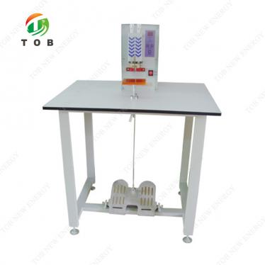
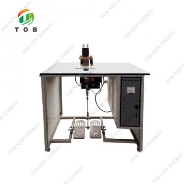
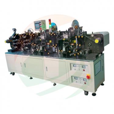
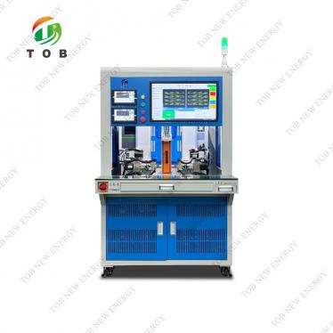
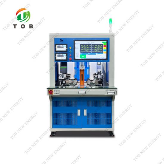
TOB-850DN-XZ-10000A AI-Driven Double-Side Automatic Spot Welding Machine for Battery Module & Pack Assembly
Product Overview and Ideal Applications
High‑speed, high‑precision resistance spot welding of nickel tabs to cylindrical cell terminals is a bottleneck in any lithium‑ion battery pack production line. Misalignment, inconsistent current, or slow cycle times directly limit throughput and can introduce weak welds that compromise pack safety. The TOB‑850DN‑XZ‑10000A is a fully automated, double‑sided spot welding machine that addresses these challenges by integrating artificial intelligence with multi‑axis servo motion control. It is purpose‑built for the repetitive, high‑volume task of welding nickel strips to the positive and negative terminals of steel‑cased cylindrical cells—18650, 21700, 26650, 32700, and others—simultaneously on both sides of the cell.
Unlike manual or single‑sided welding stations, this machine completes both end‑face welds in a single indexing cycle, achieving a factory‑set rate of 0.4 seconds per weld (9000 welds per hour), with programmable speeds up to 10,500 welds per hour. The welding power source is a 10,000 A unipolar transistor unit (with an optional 6,000 B bipolar unit effectively delivering 12,000 A), offering current‑gradient control for smooth weld nugget formation and built‑in detection of under‑current, under‑voltage, and weld splash faults.
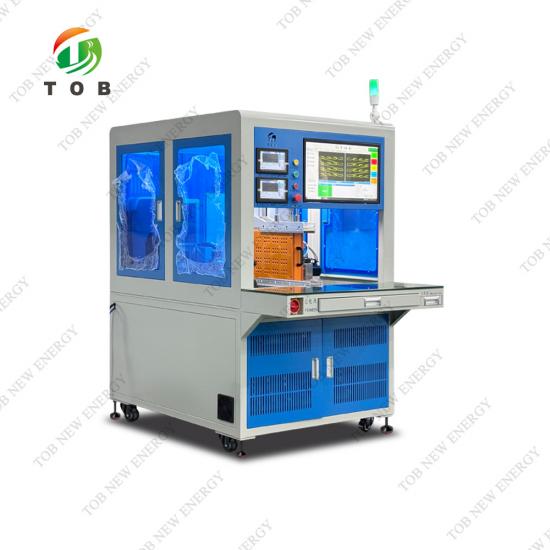
Welding accuracy is guaranteed by four servo‑driven axes (X, two Y, two R, two Z) with a positioning precision of ±0.02 mm, while AI‑based self‑correction routines automatically measure cell length, detect spot‑welding needle wear, and verify limit positions. The machine can import DXF files to generate welding paths, display real‑time weld position with colour‑coded status, and support break‑point resumption after an abnormal shutdown. With customizable barcode scanning, pressure detection, and MES data upload, it is ready for full digital traceability in a smart factory.
Ideal for:
- EV battery module and pack lines welding nickel strips to 18650, 21700, 26650, or 32700 cells in series‑parallel configurations.
- Energy storage system (ESS) pack manufacturers requiring high‑volume, consistent, and traceable spot welding for cylindrical cell assemblies.
- E‑bike, power tool, and consumer electronics battery pack producers looking to replace manual welding stations with a fully automated, inline solution.
- Any manufacturer that aims to integrate spot welding data into an MES / SCADA system for complete product genealogy.
Where This Machine Fits in Battery Pack Manufacturing
In a cylindrical‑cell‑based pack line, the process order is typically:
- Cell sorting – grouping cells by capacity and internal resistance.
- Cell insertion into fixture/holder – cells are placed into a plastic carrier that defines the module geometry.
- Spot welding of nickel strips – the strips are laid over the cell terminals and welded to create the series‑parallel electrical connections.
- BMS and voltage sensing wire attachment – often also performed by resistance welding.
- Insulation, testing, and final assembly.
The TOB‑850DN‑XZ‑10000A performs step 3, and it can also accommodate step 4 if the fixture design allows. The double‑sided welding capability is particularly valuable because a standard cylindrical cell has both a positive terminal (top cap) and a negative terminal (bottom can or integrated ring). By welding both terminals simultaneously, the machine halves the number of handling steps and eliminates the need to flip the fixture, reducing cycle time and the risk of misalignment.
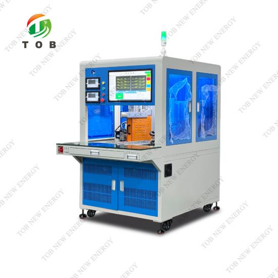
The machine’s fixture clamping system accommodates battery packs with a length of 260–680 mm, height of 260–450 mm, and a thickness that can be switched between 76.5 mm and 150 mm by changing the fixture side plates. This covers a wide range of module sizes, from small e‑bike packs to larger EV sub‑modules. The servo‑driven X‑axis (620 mm stroke) transports the fixture, while the Y‑axes align the welding heads over the cell rows, and the R‑axes rotate the welding tips to follow circular terminal patterns. The Z‑axes advance the welding needles to make contact, with a low‑speed final approach to prevent impact damage.
Integration into MES and digital manufacturing:
The machine’s industrial PC (Intel N100, 8 G RAM + 1 TB) running a proprietary control system communicates via Web/API to upload production data. Each weld event can be associated with a barcode‑scanned pack serial number, and the welding parameters (current, voltage, time, pressure) are stored locally in .xlsx format. This data forms the foundation for statistical process control, warranty analysis, and customer audits.

How the AI‑Driven Double‑Side Spot Welding System Works
Welding technology
The TOB‑850DN‑XZ‑10000A uses transistor‑based resistance spot welding. A high‑current, low‑voltage pulse is discharged through a pair of opposed spot‑welding needles that press a nickel strip against the steel cell terminal. The current pulse, precisely controlled by the transistor power supply, generates localised resistive heating at the interface, melting the nickel and bonding it to the steel. Because the heat is concentrated at the point of highest resistance (the material interface), the bulk of the cell remains cool, protecting the internal separator and electrolyte.
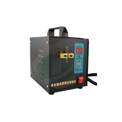
The standard configuration includes a 10,000 A unipolar transistor power supply with current gradual‑increase and gradual‑decrease functions. This shaping of the current waveform prevents sudden peaks that can cause weld spatter (explosion) or burn‑through. The power supply automatically monitors output current and voltage; if either falls outside the set range, an alarm is triggered and the machine can be stopped. An optional MIYACHI MDA‑8000B or MDB‑4000B power supply can be specified for even tighter control.
Motion control and AI self‑correction
The machine employs seven servo axes and one pneumatic pressing axis:
- X‑axis (700 W servo): moves the fixture longitudinally through the welding station (1–620 mm stroke).
- Y‑axes (2 × 700 W servo): position the welding heads along the rows of cells (1–390 mm stroke).
- R‑axes (2 × 400 W servo): rotate the welding tips (0–100°), allowing them to follow a pattern on the cell terminal.
- Z‑axes (2 × 400 W servo): advance and retract the welding needles (40–160 mm stroke, adjustable to suit cell lengths 20–150 mm).
- Pneumatic pressing axis: applies the initial clamping force before welding.

The AI self‑correction routine runs before or during welding to ensure precision:
- Length detection: The system measures the actual cell length (based on the Z‑axis position at contact) and adjusts the welding depth accordingly. If the measured length deviates from the expected value, an alarm is generated.
- Needle wear detection: Using the current and voltage signature, the AI can detect when spot‑welding needles are becoming worn or when the contact resistance has increased, preventing the production of weak welds.
- Limit detection: The AI verifies that the programmed welding positions are within the mechanical limits of the axes.
Welding path programming and visualization
The operator imports a DXF drawing of the nickel strip pattern directly into the machine software. The control system automatically extracts the welding point coordinates. Arrays can be defined as block arrays, with the ability to delete redundant points manually. During welding, the 24‑inch display shows the real‑time position of each weld: welded points are coloured blue, unwelded points yellow. This visualization allows the operator to instantly see which welds have been completed, even on a complex strip with hundreds of points.
The machine also supports regional welding(specify a range of points, e.g., 20–50, and weld only those) and break‑point resumption(after a fault, the operator enters the number of the last welded point, and the machine continues from there, eliminating the need to re‑weld completed points).
Cooling and consumables
Both welding heads are water‑cooled by a dedicated chiller (Huayou Intelligent HY‑002HP) that circulates water at approximately 6 L/min and maintains the temperature below 20 °C. This prevents the spot‑welding needles from overheating during high‑duty‑cycle operation. The standard needles are ODSC material (USA), diameter 1.7 × 100 mm; alternative diameters of 1.5 mm, 2.0 mm, and 3.0 mm are available, as well as convex‑spot needles for thicker nickel strips.
Key Engineering Advantages of the TOB‑850DN‑XZ‑10000A
- Double‑Sided Synchronous Welding Doubles Throughput - Two independent Z‑axis welding heads simultaneously weld both ends of the cell. The factory‑set rate of 0.4 s per weld (9000 welds per hour), adjustable to 10,500 welds per hour, translates into extremely short cycle times for a typical multi‑cell module. The dual‑head design effectively halves the welding time and eliminates the need for fixture inversion, reducing operator touch points.
- AI Self‑Correction Minimises Human Error and Rework - In a manual or semi‑automatic welding station, variation in cell length (even a fraction of a millimetre) can cause incomplete contact or excessive force. The TOB‑850DN‑XZ‑10000A’s AI routines continuously measure the actual cell length and needle wear, compensating for these variations in real time. The result is a dramatic reduction in weak‑weld rejection rates and the associated rework cost.
- Powerful 10,000 A Transistor Power Supply with Gradient Control - The gradual‑increase/gradual‑decrease function shapes the weld current pulse so that the nickel strip is heated gently and allowed to cool under pressure. This produces a smoother, stronger weld nugget with fewer cracks and less spatter. The automatic under‑current, under‑voltage, and weld‑splash alarms provide an additional layer of quality assurance that protects both the product and the machine.
- DXF‑Import Simplifies Programming - Instead of teaching each weld point manually, the operator simply imports the DXF file of the nickel strip layout. The control system recognises the hole positions or point markers and generates the welding program automatically. This capability is especially valuable for contract manufacturers who change pack designs frequently: a new program can be generated in minutes rather than hours.
- Full Digital Traceability and MES Integration - Every welding event is logged with timestamp, weld parameters, and barcode data, stored locally and optionally uploaded via Web/API. This creates a complete digital thread for each battery pack, from incoming cells to finished product. In the event of a field warranty return, the manufacturer can instantly verify whether the spot welds were performed within specification. The pressure‑detection option (MS2009‑20KG sensor + MI2008 converter) adds another dimension of quality data.
- Robust, Servo‑Driven Mechanics with ±0.02 mm Accuracy - The use of Xinjie servo motors and high‑precision modules (Runyang ballscrews and sliders) across all axes ensures that the welding tips always land exactly on the designated spot. The positioning accuracy of ±0.02 mm is an order of magnitude finer than the typical tolerances of manual welding jigs, guaranteeing that every weld is placed within the nickel strip’s intended target area.
- Flexible Fixture System Accommodates a Wide Range of Cell Types and Pack Sizes - The locking mechanism switches between fixture thicknesses of 76.5 mm and 150 mm, and the X‑axis travels 620 mm. Combined with the Y‑axes’ 390 mm range and the Z‑axes’ adjustable stroke, the machine can process packs from small digital‑battery clusters to large energy‑storage sub‑modules. The switching between fixture widths is mechanical and quick, minimising changeover downtime.
 |
 |
Complete Technical Specifications
Core Technical Parameters (Transistor Power Supply)
|
Model |
TOB-850DN-XZ-10000A Transistor |
|
Power Supply |
220 V, 50/60 Hz, 6 kW |
|
Air Pressure |
0.4–0.8 MPa, oil‑free and water‑mist‑free |
|
Welding Object |
Resistance welding of steel‑shell battery cells and nickel sheets (pure nickel / nickel‑plated / copper‑nickel composite sheets) |
|
Suitable Cell Types |
Length 20–150 mm, diameter 10–65 mm; e.g., 14200/14400/18650/21700/26650/32700/32140, etc. |
|
Single Cell Welding Times |
1–5 times |
|
Transistor Welding Power Supply |
10,000 A unipolar (max. 10,000 A unidirectional discharge); 6,000 B bipolar (max. 6,000 A bidirectional discharge, effective 12,000 A). Optional: MIYACHI MDA8000B/MDB4000B. Equipped with gradual increase/decrease function for welding current, ensuring smoother solder joints. Equipped with automatic output current/voltage detection, under‑current/under‑voltage alarm, and welding explosion alarm. |
|
Welding Thickness |
Pure nickel or nickel‑plated: 0.08–0.2 mm. 0.16–0.2 mm: recommended to make a diversion groove. 0.2–0.5 mm: requires convex spot welding. |
|
Welding Speed |
Factory value: 0.4 s per time (9000 times per hour). Programmable: 6000–10,500 times per hour. Adjust according to specific process and product structure. |
|
Welding Needle Configuration |
Material: ODSC. Standard spot welding needle: Ø1.7 × 100 mm; convex spot welding needle: Ø3 – 6 – 3 – 45 mm. Optional: Ø1.5 × 100 mm, Ø2.0 × 100 mm, Ø3.0 × 100 mm. |
|
Welding Needle Pressure |
1–5 kg (factory pre‑adjusted: 2.5 kg) |
|
Welding Stroke |
X‑axis (forward‑backward): 1–620 mm; Y‑axis (up‑down): 1–390 mm; R‑axis (rotation): 0–100°; Z‑axis (needle advance/retreat): 40–160 mm (suitable for cells 20–150 mm) |
|
Positioning Accuracy |
±0.02 mm |
|
Number of Axes |
One X‑axis (700 W servo motor); two Y‑axes (700 W servo motors); two R‑axes (400 W servo motors); two Z‑axes (400 W servo motors); one pneumatic pressing axis (cylinder) |
|
Control System |
Industrial PC + PLC; proprietary battery welding system |
|
Human‑Machine Interface |
24‑inch colour display; Chinese and English interface |
|
Intelligent Detection |
AI self‑correcting: length of welded object; AI self‑detects: length error of spot‑welding needles; AI self‑detects: welding limit position |
|
Welding Parameter |
Import DXF files and generate automatically (file names cannot be duplicated); array method / block array (redundant points can be manually deleted after array) |
|
Welding Path Display |
Real‑time display of current welding position: blue = welded, yellow = unwelded |
|
Regional Welding Function |
Specify the welding position, e.g., enter 20–50 points for welding from point 20 to point 50 |
|
Breakpoint Continuation |
After abnormal shutdown and fault clearance, input breakpoint position to continue welding from that point |
|
Welding Two‑Stage Speed |
Run at high speed to the set position; contact the nickel sheet and cell at low speed to prevent cell sinking and liquid leakage |
|
Welding Power Source Parameter |
Real‑time display of current welding parameters; saved on local disk |
|
Welding Needle Cooling |
Professional chiller, circulating water cooling, flow approx. 6 L/min, temperature < 20 °C |
|
Process Formula Storage |
>1000 sets of data, recallable |
|
Fixture Welding Range |
Length: 260–680 mm; height: 260–450 mm; thickness: 76.5–150 mm switchable |
|
Device Dimensions |
L1630 × W1050 × H1780 mm |
|
Packing Dimensions |
L1730 × W1280 × H1930 mm |
|
Device Weight |
Approx. 450 kg |
|
Package Weight |
Approx. 600 kg |
Customized Functions (Optional)
|
Function |
Parameter |
Detail |
|
Spot‑Welding Needle Pressure Detection |
Sensor: MS2009‑20KG; Converter: MI2008; Communication: RS232. Pressure setting: basic 2–3.5 kg (adjust per process). Pressure alarm: upper/lower limits; if exceeded, alarm and shutdown (can be deactivated). |
|
|
Production Data Upload |
Communication: Web/API. Local storage: D drive software root directory. Format: .xlsx. |
|
|
Scan‑Code Start & Multi‑PACK Data Acquisition |
Scanner: Newland OY20 + / Hikvision MV‑IDH3000/13NR/05RN/U. Interface: USB. Barcode formats: 1‑D (e.g., CODE 128), 2‑D (e.g., QR CODE). Multi‑PACK per fixture: scan multiple barcodes sequentially; generate corresponding barcode data after welding. Local storage: D drive, .xlsx. |
|
|
Welding Coordinate AI Visual Recognition |
Optional. |
Recommended Welding Parameters (Starting Points)
These are typical settings for a standard 18650 cell with 0.15 mm pure nickel strip. The final parameters must be optimised for your specific cell, strip material, and pack design.
|
Parameter |
Starting Value |
Notes |
|
Welding current (unipolar) |
200–400 A (based on required current density) |
Start low and increase until full‑size nugget is achieved. |
|
Weld time (per pulse) |
5–15 ms |
Too long can cause burn‑through; too short results in weak bond. |
|
Needle pressure |
2.5–3.5 kg |
Maintain consistent pressure; pressure detection option enables closed‑loop monitoring. |
|
Number of pulses per spot |
1–3 |
Multi‑pulse often used for thick nickel strips. |
|
Cooling water temperature |
< 20 °C |
Check chiller flow regularly. |
|
Z‑axis low‑speed approach distance |
2–3 mm |
Prevents impact damage to cell. |
Always perform destructive peel‑test and cross‑sectional analysis on the first articles of each new setup to validate the weld quality.
Common Welding Issues and Troubleshooting
|
Issue |
Possible Cause |
Solution |
|
Weak weld (easily peeled) |
Insufficient current, low pressure, or worn needles. |
Increase current in small steps. Check needle pressure setting and verify sensor calibration if pressure detection is installed. Replace worn ODSC needles. |
|
Weld spatter (molten metal ejection) |
Excessive current or contact resistance spike due to dirty electrodes. |
Reduce current or enable gradual‑increase function. Clean the cell terminals and nickel strip with alcohol. Ensure needles are properly aligned. |
|
Burn‑through of nickel strip |
Current too high or weld time too long for the strip thickness. |
Reduce current and/or time. For thickness >0.2 mm, use a convex spot‑welding needle and consider diversion grooves. |
|
Inconsistent weld quality across the pack |
Misalignment of the fixture; worn Z‑axis module; variation in cell height. |
Verify that the fixture is properly locked and that the cells are fully seated. Run the AI length‑detection routine and check needle wear. Calibrate the Z‑axis stroke. |
|
Machine stops with “under‑current” alarm |
Power supply not reaching set current due to poor electrical connection or high resistance in the secondary circuit. |
Check all cable connections from the power supply to the welding heads. Clean the electrode holders. Inspect the transistor power supply for faults. |
|
Water leakage near welding head |
Damaged cooling tube or loose fitting. |
Immediately stop the machine and repair the leak. The chiller flow rate should be checked—6 L/min is typical. |
|
DXF import fails or welding points are out of position |
File name conflict or incorrect scaling in DXF. |
Ensure file names are unique. Verify that the DXF is drawn in millimetres, and that the origin corresponds to the fixture zero point. Re‑import after correcting. |
Engineering FAQ — Automated Spot Welding for Battery Packs
Q1: Can this machine weld copper‑nickel composite strips, or only pure nickel?
The machine is specified for pure nickel, nickel‑plated, and copper‑nickel composite sheets. Copper‑nickel composites have higher conductivity and lower contact resistance than pure nickel, but they require a higher welding current and may need convex‑point needles to concentrate the current. The 10,000 A power supply is capable of welding these materials, but we recommend running a weldability trial with your specific composite grade.
Q2: How does the machine handle cells of different lengths in the same fixture?
The AI length‑detection routine measures each cell individually when the Z‑axis makes first contact and adjusts the stroke accordingly. This means that cells within a single fixture can vary somewhat in length without requiring manual reprogramming. However, for optimum consistency, cells should be pre‑sorted by length and capacity.
Q3: What happens if a cell is missing or misaligned in the fixture?
The AI limit‑detection function will notice that the Z‑axis stroke is out of the expected range and will trigger an alarm. The machine can be programmed to stop and alert the operator, or to skip that particular weld spot if the cell is absent. This prevents damage to the welding head and to the fixture.
Q4: Is the MES integration complicated?
The machine provides a Web/API interface for data upload. As long as your MES can accept data via these protocols, integration is straightforward. The data is stored locally in a standard .xlsx format on the D drive, so even without MES, you can access full production records by plugging a USB drive or connecting over the network.
Q5: How often should the spot‑welding needles be replaced, and can they be re‑sharpened?
ODSC needles have a long service life when properly cooled and when the welding parameters are within the recommended range. Under high‑volume production (several thousand welds per day), needles may last several weeks. They can be lightly dressed, but it is generally more economical to replace them when the tip geometry begins to change significantly. The AI needle‑wear detection provides an early warning before weld quality is affected.
Why Choose TOB‑850DN‑XZ‑10000A Over Manual or Semi‑Automatic Welding Stations
|
Feature |
TOB‑850DN‑XZ‑10000A |
Manual/Semi‑Automatic Spot Welder |
|
Welding throughput |
0.4 s per weld, up to 10,500 welds/h |
Typically 3–5 s per weld (including fixture handling) |
|
Weld consistency |
±0.02 mm positioning, AI length correction, current gradient control |
Heavily operator‑dependent; frequent weak welds |
|
Data traceability |
Full MES integration, barcode scanning, .xlsx export |
None, or at most a counter |
|
Double‑side welding |
Simultaneously welds both terminals |
Requires flipping the fixture manually |
|
Changeover time |
DXF import, fast fixture width switching |
Manual reprogramming or teaching |
|
Error prevention |
AI self‑correction for cell length, needle wear, limit positions |
Relies on operator vigilance |
|
Cooled welding heads |
Circulating water chiller, continuous duty |
Air‑cooled, limited duty cycle |
|
Suitability for EV/ESS production |
Fully production‑ready |
Suitable for prototype or low‑volume only |
Why upgrade:
The jump from manual spot welding to the TOB‑850DN‑XZ‑10000A is not merely a speed improvement—it is a quality transformation. In a manual process, the operator must judge the pressure, alignment, and weld time by feel, leading to a spread of weld strengths that only becomes apparent during full‑pack cycling tests. The TOB‑850DN‑XZ‑10000A replaces that variability with servo‑actuated precision and AI‑verified quality, ensuring that every weld in a 10,000‑weld module is indistinguishable from the rest. When that module is assembled into an EV battery pack and expected to last 10 years, that consistency is non‑negotiable.

Installation, Commissioning, and Training
- Installation: Unless otherwise agreed, the buyer is responsible for receiving, unpacking, and transporting the machine to the installation site, as well as preparing the electrical connections.
- Commissioning: The seller is responsible for equipment installation, debugging, and system integration with the buyer’s production line peripherals.
- Trial production: After installation, a small‑scale trial production run is conducted with the buyer’s cells and nickel strips. Formal mass production begins only after the test pieces are approved by the buyer’s quality department.
- Training: The seller provides free training for the buyer’s operators and maintenance staff. Training content includes: normal operation, routine maintenance, fault analysis and troubleshooting, operational safety, and emergency shutdown procedures.
Operating Environment
|
Parameter |
Requirement |
|
Ambient temperature |
–10 °C to +55 °C |
|
Relative humidity |
≤ 75 % |
|
Factory environment |
No corrosive gases, no strong electromagnetic interference |
Ready to move your cylindrical‑cell pack assembly from manual stations to a fully automated, traceable spot‑welding line? Request a quotation for the TOB‑850DN‑XZ‑10000A. Provide your cell type, module layout DXF, and target throughput; our automation team will return a detailed welding feasibility study and cycle‑time analysis.
tob.amy@tobmachine.com | +86 181 2071 5609
You May Also Need
- TOB-IP-3000A Inverter DC Spot Welding Machine
- TOB-SW-8000A-500 Automatic Single-side Cylindrical Battery PACK Spot Welding Machine
- TOB-SWR Pneumatic Punching Machine for Spot Welds Remove
- TOB-HDP-3000S Manual Spot Welding Machine
Previous:
Automatic Spot Welding 18650 Cells Single Side Spot Welding MachineNext:
Automatic Double Side Spot Welding Machine for Battery Pack
If you are interested in our products and want to know more details,please leave a message here,we will reply you as soon as we can.