Chinese
 français
 Deutsch
 italiano
 español
 português
 Nederlands
 日本語
日本語 한국의
한국의




- Home
- >
18650 Battery Pack Assembly Equipment
- >
Battery Pack Welding Machine
- >
Electric Intelligent Transistor Spot Welder 10000A | TOB-550D-10000A
Categories
Hot Products
Loading...
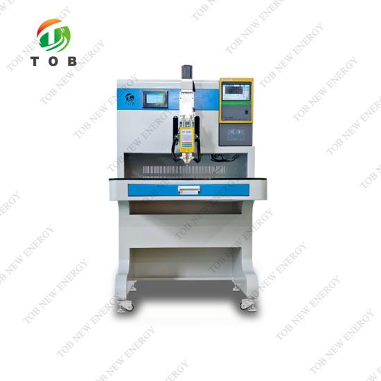
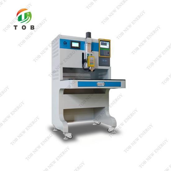
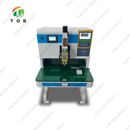
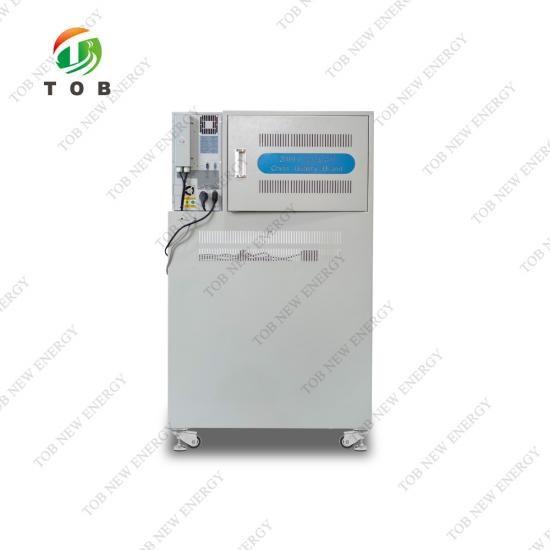
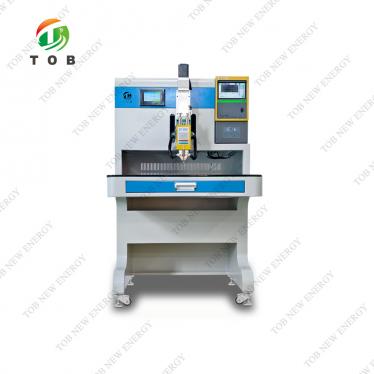
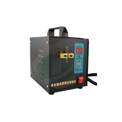
Electric Intelligent Transistor Spot Welder 10000A | TOB-550D-10000A
Brand:
TOB NEW ENERGYitem no.:
TOB‑550D‑10000Aorder(moq):
1setPayment:
L/C,T/Tproduct origin:
Chinashipping port:
XIAMEN
TOB-550D-10000A Electric Intelligent Transistor Series Resistance Spot Welder with DSP Control
Product Overview and Ideal Applications
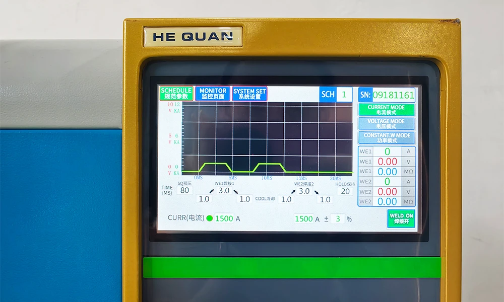
The TOB‑550D‑10000A is an electric intelligent transistor series resistance spot welder that uses DSP (digital signal processor) control technology to deliver precisely regulated welding current under constant‑current, constant‑voltage, or constant‑current/constant‑voltage modes. The DSP continuously monitors the welding current and voltage, automatically triggering an alarm if the measured values fall outside the user‑set under‑current, under‑voltage, over‑current, or over‑voltage limits. A touch‑screen interface provides intuitive access to all settings, and multiple built‑in self‑test routines verify the system status before each welding cycle.
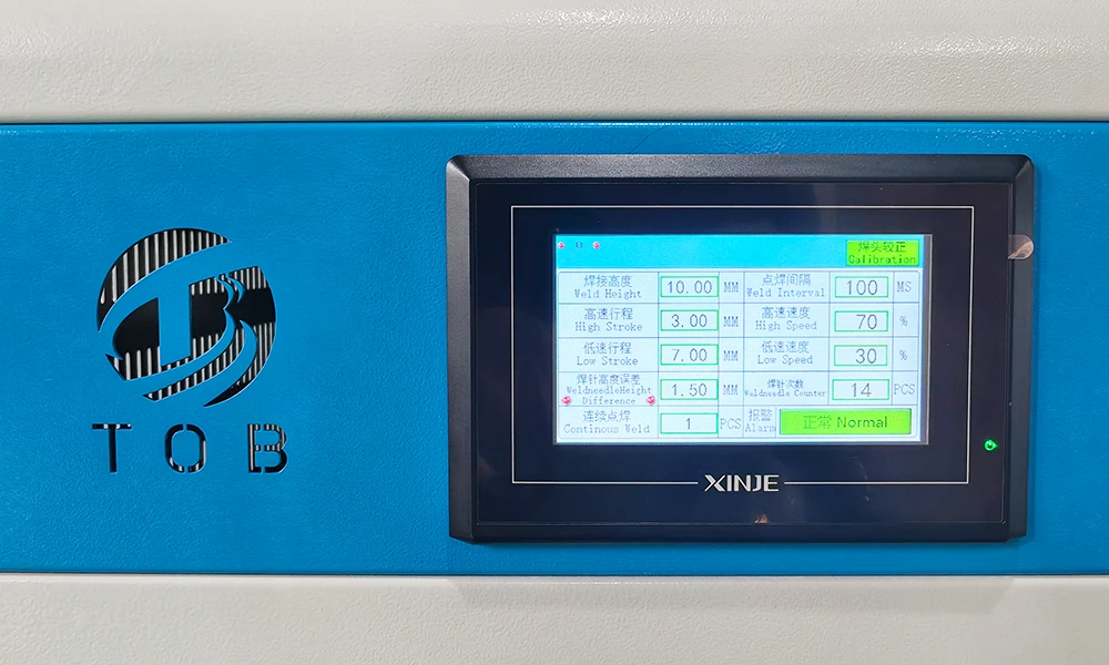
Unlike pneumatic spot welders that require a compressed‑air supply, the TOB‑550D‑10000A drives its welding head with a 400 W servo motor, giving the operator fully electric control over the welding stroke, height, and buffer pressure. The welding height can be intelligently calibrated with a single touch on the screen, and the buffer stroke is adjustable from 7 mm to 60 mm, with the buffer force independently adjustable from 0.5 kg to 5.5 kg. An integrated length‑difference detection system automatically measures the installed length of the two spot‑welding electrodes and triggers an alarm if the difference exceeds a programmed tolerance, while a built‑in induction limit switch prevents the welding head from over‑travelling and crushing the workpiece.
The welding current is provided by a user‑selected transistor welding power supply; the TOB‑550D‑10000A can be equipped with a BTH‑5000A (5000 A single‑wave), BTH‑5000B (5000 A positive‑and‑negative‑wave, effectively 10,000 A), or BTH‑10000A (10,000 A single‑wave) unit. The actual output current is transmitted to the welding electrodes through pure‑copper cables of 120 mm² cross‑section (up to an adaptor) and 75 mm² cross‑section (to the electrode clamps). A pressure‑adjustment knob, lockable with a nut, sets the contact force between the electrodes and the workpiece; the factory recommendation is 2.5 kg, but the optimal value depends on the welding current and must be tuned for each application.
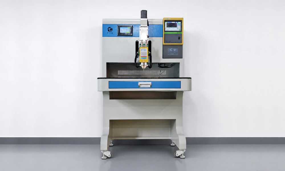
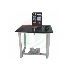
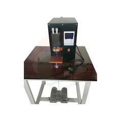
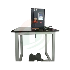
The TOB‑550D‑10000A is compact (L 760 mm × W 800 mm × H 1380 mm) and mobile, mounted on lockable castors. The worktable is made of 10 mm tempered glass, providing a smooth, non‑conductive surface that simplifies positioning of the workpiece. The maximum workpiece size that can be accommodated is L 400 mm × W 300 mm × H 155 mm.
Ideal for:
- Welding nickel tabs to cylindrical and prismatic lithium‑ion cells during battery pack assembly, including power batteries for EVs, energy storage systems, and digital consumer electronics.
- Joining Ni‑MH and Ni‑Cd cells in high‑power battery packs where the electrode‑to‑cell contact must be low‑resistance and mechanically robust.
- Motor‑rotor winding termination, electronic component lead‑to‑lead welding, and general electrical accessory assembly where a consistent, high‑quality spot weld is required.
- Production environments that cannot tolerate the maintenance and noise of a pneumatic system and prefer an all‑electric, servo‑driven welding head for cleaner, more controllable operation.
Key Components and Operating Principles
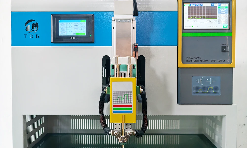
The TOB‑550D‑10000A integrates the following major components, each contributing to the precision and reliability of the spot‑welding process:
| No. | Component | Description |
| 1 | Welding power supply | A necessary component. Optional models: BTH‑5000A (5000 A single‑wave), BTH‑5000B (5000 A positive‑and‑negative‑wave, effectively 10,000 A), BTH‑10000A (10,000 A single‑wave). Refer to the Welding Power Supply Instruction Manual for detailed specifications. |
| 2 | Origin sensor | Connects to the welding power supply (24 V+ / signal / 24 V−). If the sensor is not connected or is damaged, the welding power supply will issue an alarm during start‑up detection. |
| 3 | Servo motor | A 400 W, 220 V, 50 Hz servo motor that drives the welding module up and down. It automatically resets to the origin when the welding power supply is switched on. |
| 4 | Welding module | Driven by the servo motor through a lead screw, the welding head slides on dual guide‑rail sliders for stable, vibration‑free movement. |
| 5 | Pressure adjustment knob | Sets the pressing force between the spot‑welding electrodes and the workpiece. The basic factory setting is 2.5 kg. After adjustment, the knob should be locked with the nut to prevent drift during welding. Excessive pressure can indent the workpiece, while insufficient pressure can cause sparking during high‑current discharge. Higher welding currents generally require higher contact pressure. |
| 6 | Welding head | Moves down to contact the workpiece. It consists of a pressure regulator, upper and lower guide‑rail sliders, and the welding‑electrode clamps. The electrode clamps are made of two independent nickel‑plated copper parts to improve electrical conductivity and resist oxidation. The stroke of the welding head is 35–155 mm; the appropriate height for the workpiece is set electrically via the intelligent control system. |
| 7 | Tool box | Stores common tools, spare spot‑welding electrodes, and other accessories. |
| 8 | Welding cable | Transmits the output of the spot‑welding power supply to the electrodes. A 120 mm² pure‑copper cable is used from the power supply to an adaptor, and a 75 mm² pure‑copper cable runs from the adaptor to the electrode clamp. All screws must be kept tight; loosening can cause a power‑supply alarm or unstable welding current. |
| 9 | Welding electrode clamp | Made of nickel‑plated copper for improved conductivity and oxidation resistance. The two upper screws (M6 × 16) can be loosened to adjust the centre‑to‑centre distance of the two electrodes; the recommended minimum spacing is > 3.5 mm. An excessively small distance risks short circuits or blackening of the weld area. The four lower screws (M6 × 16) allow the exposed length of the electrodes to be set; the optimal value is usually 12 mm, and it is recommended to keep it within 20 mm for special applications. |
| 10 | Worktable surface | A 10 mm tempered‑glass platform on which the workpiece is placed. The glass surface allows easy manual repositioning of the workpiece. Maximum workpiece dimensions: L 400 mm × W 300 mm × H 155 mm. |
| 11 | Castor with brake | The whole machine is moved on castors. Once in position, the adjustable foot cups or the castor brakes are used to secure the machine. |
Operating logic:
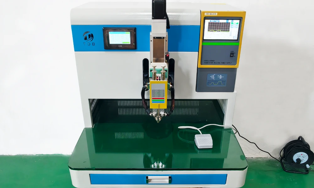
When the welding sequence is initiated, the servo motor drives the welding head downward until the electrodes contact the workpiece with the pre‑set buffer pressure. The DSP then delivers the programmed welding current pulse—either a single‑wave or a positive‑negative‑wave pulse, depending on the selected power‑supply model—while simultaneously monitoring the current and voltage. After the pulse, the head retracts, and the control system checks the monitored values against the alarm thresholds before indicating that the weld is complete. The entire cycle is executed without compressed air, relying solely on the servo drive and the DSP‑controlled transistor output stage.
Key Intelligent Features
The following features are specified for the TOB‑550D‑10000A and distinguish it from conventional pneumatic or timer‑based spot welders:
- DSP‑based precision control: The welding energy can be controlled in three modes—constant current, constant voltage, or constant current and constant voltage—giving the process engineer the flexibility to select the regulation strategy that best matches the material pair and the required weld quality.
- Automatic current and voltage monitoring with alarm: The system continuously measures the actual current and voltage during each weld. If the values fall below or exceed the user‑defined under‑current, under‑voltage, over‑current, or over‑voltage thresholds, an alarm is immediately triggered, allowing defective welds to be identified and the process to be stopped if necessary.
- Electric servo drive – no air supply needed: The 400 W servo motor and lead‑screw mechanism replace the pneumatic cylinder found in conventional spot welders. This eliminates the need for a compressed‑air system, reduces noise, and provides finer control over the welding head speed and position.
- One‑touch intelligent height calibration: The operator can set the welding height with a single touch on the screen; the system then automatically calibrates the head position for the specific workpiece, removing the need for manual gauge‑block adjustments.
- Automatic electrode length‑difference detection: Before welding, the system compares the lengths of the two installed spot‑welding electrodes. If the difference exceeds the programmed limit, an alarm is raised, preventing the asymmetric welds that can result from uneven electrode wear or incorrect installation.
- Induction limit alarm to prevent cell crushing: A built‑in induction limit sensor stops the welding head if it travels beyond the safe height, protecting the workpiece from being crushed—especially important when welding delicate cells such as cylindrical or pouch batteries.
- Configurable continuous welding (1–10 times): For applications requiring multiple pulses on the same spot, the number of consecutive welding cycles can be set between 1 and 10. This multi‑pulse capability is useful for conditioning the weld nugget or for welding thicker tab materials.
- Adjustable buffer stroke and pressure: The buffer stroke (7–60 mm) and the buffer pressure (0.5–5.5 kg) are independently set, allowing the welding head to gently contact the workpiece before the full pressure is applied and the current pulse is triggered.
- Fault diagnosis and automatic protection: If the controller detects an abnormal condition during operation, it automatically cuts off the output and provides an alarm indication, protecting both the machine and the workpiece.
Complete Technical Specifications
The following table consolidates the technical parameters of the TOB‑550D‑10000A as stated.
| Parameter | Specification |
| Power Supply | AC 220 V, 50/60 Hz, 1 kW |
| Transistor Welding Power Supply (Optional) | BTH‑5000A (5000 A single‑wave), BTH‑5000B (5000 A positive‑and‑negative‑wave, i.e. 10,000 A), BTH‑10000A (10,000 A single‑wave) |
| Suitable Welding Scope | Power batteries, digital batteries, Ni‑MH and Ni‑Cr batteries, motor rotors, electronic and electrical accessories, etc. |
| Interface Display | Touch screen with intuitive operation |
| Welding Power (Actuation) | Servo electric (no air source connection required) |
| Welding Height Calibration | One‑touch intelligent setting |
| Electrode Length‑Difference Detection | Automatic; alarm when the installed length difference of spot‑welding electrodes exceeds the set value |
| Induction Limit Alarm | Built‑in; prevents cell crushing in case of incorrect welding height |
| Continuous Welding Setting | Configurable, 1–10 times |
| Welding Head Height Adjustment Range | 30–155 mm (intelligent self‑calibration) |
| Spot‑Welding Electrode Buffer Stroke | 7–60 mm (freely set; 10 mm for standard products) |
| Spot‑Welding Electrode Buffer Pressure | 0.5–5.5 kg, adjustable |
| Fault Diagnosis and Automatic Protection | In case of abnormal conditions, automatic output cut‑off and alarm |
| Overall Dimensions | L 760 × W 800 × H 1380 mm |
| Weight | Approx. 80 kg |
| Worktable Material | 10 mm tempered glass |
| Max. Workpiece Size | L 400 × W 300 × H 155 mm |
| Welding Cable | 120 mm² pure‑copper cable to adaptor, 75 mm² pure‑copper cable to electrode clamp |
| Electrode Clamp Material | Nickel‑plated copper |
| Electrode Clamp Optional Models | Φ1.5 mm / Φ1.7 mm / Φ2.0 mm / Φ3.0 mm |
| Spot‑Welding Electrode Optional Models | Φ1.5 mm / Φ1.7 mm / Φ2.0 mm / Φ3.0 mm eccentric electrodes, Φ3.0 mm convex spot‑welding electrodes |
| Centre‑to‑Centre Electrode Distance (Recommended) | > 3.5 mm |
| Recommended Electrode Exposed Length | 12 mm (max. 20 mm for special applications) |
| Mobility | Castors with brakes and adjustable foot cups |
Practical Setup and Operation Recommendations
The following guidance is based on the welding machine's instructions and helps to achieve consistent weld quality with the TOB‑550D‑10000A:
- Electrode installation and spacing: Always ensure that the two electrodes are separated by at least 3.5 mm centre‑to‑centre. A spacing narrower than this can cause a direct short circuit between the electrodes, which results in a current path that bypasses the workpiece entirely. It also tends to blacken the weld area. Use the two upper M6 screws to adjust and secure the spacing.
- Electrode exposure: Set the exposed length of the electrodes to approximately 12 mm using the four lower M6 screws. For workpieces that require a longer reach, the exposure can be extended up to 20 mm, but longer exposures increase the electrical resistance of the path and can reduce the effective welding current.
- Pressure adjustment: The factory default pressure setting of 2.5 kg is a good starting point for many applications. Increasing the pressure improves electrical contact and reduces sparking, but too much pressure can leave a deep indentation on the cell terminal or tab. As a rule of thumb, higher welding currents require higher contact pressure. After adjusting the pressure knob, always lock it with the nut to prevent drift during welding.
- Welding height calibration: Use the one‑touch height calibration function whenever the workpiece type is changed. The induction limit alarm will stop the head before it can crush a cell, but the correct height setting also ensures that the buffer stroke operates within its intended range, giving the optimum balance between approach speed and contact gentleness.
- Cable connections: Inspect the welding cable connections regularly. The high currents involved (up to 10,000 A) cause significant heating at any point of increased resistance, such as a loose screw or a corroded contact. Tighten all connections to the specified torque and replace any cable that shows signs of discolouration or fraying.
- Electrode maintenance: Spot‑welding electrodes wear over time, particularly at the tip. The automatic electrode length‑difference detection system will alert the operator when the difference between the two electrode lengths exceeds the set tolerance, indicating that one or both electrodes need to be dressed or replaced. Keep a stock of replacement electrodes in the toolbox provided with the machine.
Engineering FAQ
Q1: Which transistor power supply should I choose – 5000 A, 5000 B, or 10000 A?
The choice depends primarily on the material and thickness to be welded. A 5000 A single‑wave supply is sufficient for many thin nickel tab‑to‑cell welding tasks with tabs up to 0.15 mm. The 5000 B configuration, which produces a positive‑and‑negative‑wave output effectively delivering 10,000 A, provides a bipolar pulse that can help to reduce spatter and improve weld nugget symmetry. The 10000 A single‑wave supply is recommended for thicker tabs (0.2 mm and above) and for applications where a single, high‑energy pulse is preferred.
Q2: What is the purpose of the buffer stroke and buffer pressure, and how should they be adjusted?
The buffer stroke allows the welding head to descend rapidly to a position just above the workpiece, then continue slowly under controlled pressure for the final contact. This two‑stage approach prevents the electrode from striking the workpiece with excessive force. The buffer stroke should be set so that the electrodes contact the workpiece gently, and the buffer pressure should be adjusted to achieve the desired contact force as indicated on the pressure adjustment knob. A typical starting point is a buffer stroke of 10 mm and a buffer pressure of 2.5 kg.
Q3: Can the TOB‑550D‑10000A weld copper directly to steel, or is nickel plating required?
The machine is designed to resistance‑weld nickel and nickel‑plated materials to steel and other metals. Welding bare copper to steel is more challenging due to copper's high conductivity and low resistance; a higher current and a larger electrode contact area are usually required. In battery applications, nickel‑plated copper tabs are commonly used, and the TOB‑550D‑10000A handles these well. If your application involves direct copper‑to‑steel welding, a test with the appropriate power supply and electrode configuration is recommended.
Q4: How should I clean the tempered‑glass worktable, and is it resistant to accidental impact?
The worktable can be cleaned with a soft cloth and a mild glass cleaner. Avoid abrasive cleaners that could scratch the surface. Tempered glass is resistant to moderate impacts, but dropping a heavy workpiece or a tool directly onto the table could cause chipping or cracking. If the table is damaged, it should be replaced promptly to maintain a flat, non‑conductive working surface.
Q5: Does the machine require regular calibration, and how is it performed?
The DSP control system maintains its calibration over long periods. The primary maintenance items are the electrode length‑difference zero‑point and the origin sensor. The origin sensor is checked automatically at each power‑on; if a fault is indicated, check the sensor connection and alignment. Electrode length calibration is performed by the built‑in detection system whenever new electrodes are installed. For a comprehensive verification of the welding current and voltage accuracy, an annual check with a calibrated current probe and voltmeter is recommended.
Ready to upgrade your spot‑welding process to an all‑electric, DSP‑controlled system with intelligent height calibration and electrode monitoring? Request a quotation for the TOB‑550D‑10000A, configured with the transistor power supply that matches your application. Our welding engineers can also advise on electrode selection and starting‑point parameters for your specific materials.
tob.amy@tobmachine.com | +86 181 2071 5609
You May Also Need
- Double‑Side Automatic Spot Welder for Battery Pack Assembly - A high‑throughput, fully automatic double‑side spot welding station for production‑scale cylindrical battery pack assembly. Complements the TOB‑550D‑10000A by providing automated, high‑speed dual‑side welding for large‑format modules, reducing manual handling and increasing line efficiency.
- Automatic Single‑Side Spot Welding Machine for 18650 Cells - An automatic single‑side spot welder optimised for 18650 cell packs. Offers a compact, cost‑effective solution when only one side of the cell array requires welding—can be used in tandem with the TOB‑550D‑10000A for applications where the second side is welded by a dedicated machine.
- Manual Spot Welding Machine - A manually operated spot welding station for low‑volume production, prototype builds, and rework. Complements the TOB‑550D‑10000A by providing a flexible, hand‑guided option for tasks that do not require the full automation or high throughput of the servo‑controlled system.
Previous:
Automatic Spot Welding 18650 Cells Single Side Spot Welding MachineNext:
Double-Side Auto Spot Welder for Battery Pack Assembly
If you are interested in our products and want to know more details,please leave a message here,we will reply you as soon as we can.


 subscribe to us