
- Home
- >
Dry Electrode Film Solution
- >
Dry Electrode Film Forming Machine for Battery R&D
Categories
Hot Products

Loading...
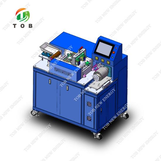
Dry Electrode Film Forming Machine for Battery R&D
Brand:
TOB NEW ENERGYitem no.:
TOB-HRPE200-3ALorder(moq):
1Payment:
L/C,T/Tproduct origin:
Chinashipping port:
XIAMEN
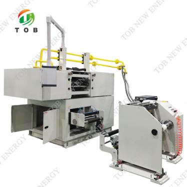
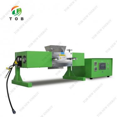
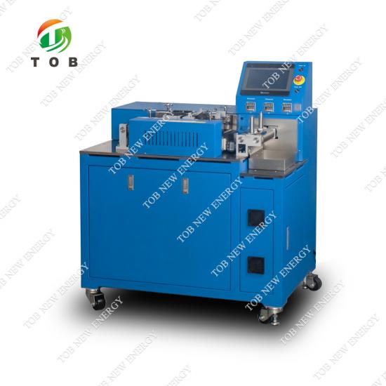
Dry Electrode Film Forming Machine for Battery R&D | TOB-HRPE200-3AL
Product Overview and Ideal Applications
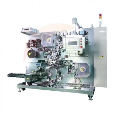
A dry electrode film forming machine—often called a heated roller press or calender—converts a free‑flowing powder mixture of active material, conductive carbon, and fibrillizable binder (typically PTFE) directly into a self‑supporting electrode film without the use of solvents, slurry mixing, or lengthy drying steps. The TOB‑HRPE200‑3AL is a benchtop‑to‑pilot‑scale machine purpose‑built for this solvent‑free electrode manufacturing route. It applies controlled temperature and precisely adjustable roll‑gap pressure to densify and fibrillate the powder into a continuous film that can be laminated directly onto a current collector, drastically simplifying the electrode production chain.
The machine employs two precision‑ground steel rollers (Ø96 mm) with a surface hardness of HRC62, achieved through hard‑chrome plating. The chromium layer not only resists abrasive wear from the electrode powder but also prevents rust during ambient storage, a practical concern in busy laboratories. The rollers are internally heated from room temperature to 130 °C, with each roller independently controlled and digitally displayed. Temperature uniformity is critical because the PTFE binder must be brought to its fibrillation temperature—typically between 60 °C and 120 °C—without overshooting to a point where the active material degrades. The roller cylindricity of ≤ ±2 µm ensures that the roll gap, and therefore the film thickness, is consistent across the entire 200 mm working width.
Ideal for:
- Battery R&D groups and pilot lines developing solvent‑free (dry) electrode manufacturing processes for lithium‑ion, sodium‑ion, and solid‑state batteries.
- Researchers investigating the fibrillation behaviour of PTFE or other fibrillizable binders with NMC, LFP, graphite, hard carbon, or silicon‑based active materials.
- Manufacturers evaluating dry electrode technology as a means to eliminate toxic NMP solvent, reduce energy‑intensive drying, and lower factory footprint.
- Material scientists needing a compact, instrumented roller press to produce uniform, thickness‑controlled films for coin‑cell, single‑layer pouch‑cell, or small‑format cylindrical cell testing.
- Any lab that has attempted dry electrode processing with a manual hydraulic press and found the process inconsistent, poorly controlled, and unsuitable for scaling.
Where This Machine Fits in Dry Electrode Manufacturing
Traditional lithium‑ion battery electrodes are made by wet processing: the active powder, carbon, and binder are mixed into a slurry with NMP (for cathodes) or water (for anodes), coated onto a metal foil, and then passed through long drying ovens to remove the solvent before calendaring. This route consumes significant energy, requires solvent recovery systems, and limits the use of certain materials (e.g., metallic lithium or sodium) that react with water.
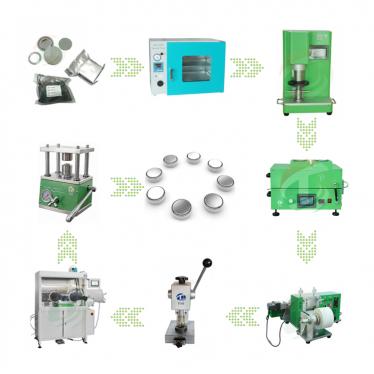
Dry electrode processing eliminates the solvent entirely. The workflow typically proceeds as follows:
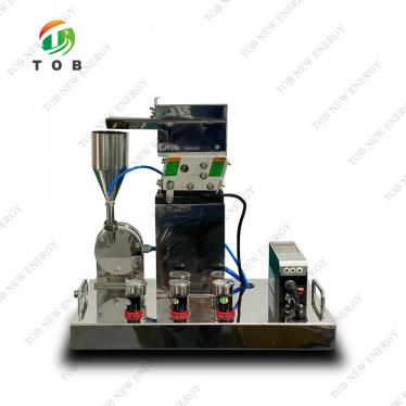
- Dry blending: Active material, conductive carbon, and PTFE powder are intimately mixed in a high‑shear dry mixer. The PTFE particles are stretched into fine fibrils during mixing, forming a web that holds the powder together.
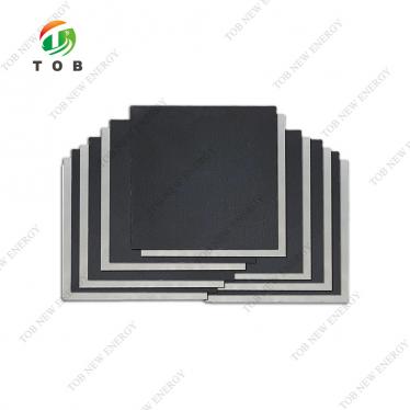
- Film forming (the TOB‑HRPE200‑3AL’s role): The free‑flowing powder is fed between the pair of heated, counter‑rotating rollers of the TOB‑HRPE200‑3AL. The combination of heat, pressure, and shear further fibrillates the PTFE and compacts the powder into a continuous, self‑supporting film of controlled thickness. The rollers rotate at independently adjustable speeds (0–1 rev/s), enabling a shear component that enhances densification.
- Lamination: The formed dry film is then laminated directly onto a current collector (aluminium or copper foil) in a second calendering step—or in the same machine by feeding the foil together with the powder. This produces a finished electrode sheet.
- Slitting / cutting: The integrated slitting knife trims the edges of the film to the desired width, and the winding mechanism collects the finished film or electrode onto a 3‑inch air shaft for further processing.
The TOB‑HRPE200‑3AL performs steps 2 and partially step 3 (if the current collector is fed along with the powder) and step 4, in a continuous operation. Because there is no solvent, there is no drying oven, no solvent recovery, and no binder‑migration defects that occur during slow wet‑film drying. The film thickness uniformity is determined directly by the roll‑gap precision, which in this machine is controlled digitally and displayed by an electronic dial gauge.
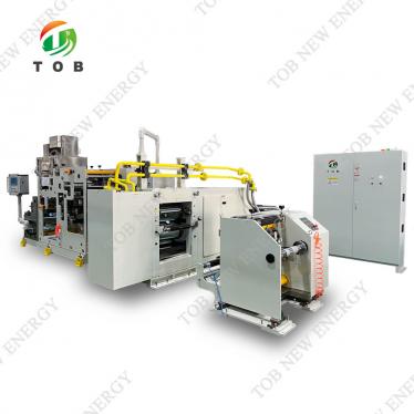
How the Heated Roller Press and Film Forming Process Works
The TOB‑HRPE200‑3AL is built around a pair of Ø96 mm precision‑ground steel rollers mounted on high‑precision bearings (IFU, Sweden). Each roller is internally heated using an electric cartridge system, with the temperature set independently via Autonics digital temperature controllers. The roller surface is plated with hard chromium to a hardness of HRC62, providing a smooth, wear‑resistant surface that minimises powder adhesion and resists corrosion.
Drive and speed ratio control
Two servo motors (Inovance) drive the rollers independently. This is a critical design feature: unlike a simple geared calender, the TOB‑HRPE200‑3AL can operate the rollers at different speeds, creating a controlled shear field in the nip region. For dry electrode powders, a small speed differential (e.g., 5–15 %) imparts additional shear that promotes PTFE fibrillation and produces a denser, more coherent film. The speed of each roller is adjustable from 0 to 1 revolution per second via the PLC and displayed on the Weintek touch screen. The direction of rotation can also be set independently.
Roll gap adjustment and thickness control
The gap between the two rollers—and therefore the film thickness—is adjusted from 0 to 2 mm using a stepper‑motor‑driven automatic gap adjustment mechanism (Leadshine stepper motor). The mechanism has excellent self‑locking performance, meaning the gap does not drift during rolling, even under the considerable separating force generated by the compacting powder. The actual gap is displayed on an electronic digital dial gauge, providing micron‑level feedback to the operator. The roller cylindricity of ≤ ±2 µm ensures that the measured gap at the centre of the rollers is representative of the gap across the full 200 mm working width, a specification that is unusually tight for a benchtop‑scale machine and directly translates into exceptional film thickness uniformity.
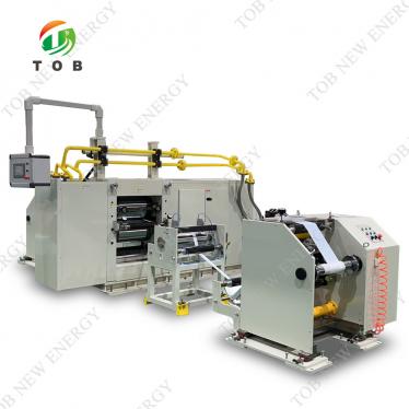
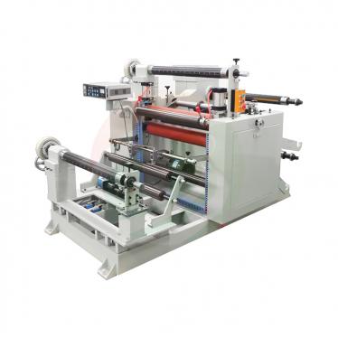
Winding, unwinding, and slitting
The machine is equipped with a winding and unwinding correction mechanism that maintains proper web alignment. If a current collector foil or a pre‑formed film is being fed into the nip, the unwinding device with conveyor‑belt‑assisted feeding ensures wrinkle‑free entry. After the film exits the nip, an integrated slitting knife trims the edges to the desired width, and the finished film is wound onto a 3‑inch air shaft (max. roll diameter 200 mm). This enables truly continuous operation: powder in, trimmed electrode film out.
PLC and control architecture
The entire machine is controlled by a PLC (Inovance or Panasonic) through a Weintek touch‑screen HMI. The operator sets the roller temperatures, roller speeds (and speed ratio), gap, and winding tension on one screen. The PLC coordinates the servo drives, the stepper gap motor, and the winding/unwinding motors, and it monitors the temperature controllers, solid‑state relays (Yangming), and circuit protection devices (Chint). Izumi relays provide signal‑level isolation for the control circuits.
Key Engineering Advantages for Dry Electrode Processing
- Independent Roller Heating and Precise Temperature Control (Room Temp. to 130 °C) — PTFE fibrillation is strongly temperature‑dependent. If the roller temperature is too low, the PTFE particles do not soften sufficiently and the film lacks mechanical strength. If the temperature is too high, the active material may begin to decompose, or the PTFE may over‑fibrillate and lose porosity. The TOB‑HRPE200‑3AL’s dual‑zone digital temperature control (Autonics, Korea) allows the operator to maintain each roller at a precise, independently set temperature, ensuring that the material experiences exactly the thermal profile required.
- Asynchronous Roller Rotation with Adjustable Speed Ratio for Enhanced Densification — The independent servo drive of each roller permits a speed differential (e.g., 0.9 rev/s on the upper roller and 1.0 rev/s on the lower). This introduces a shear component that physically stretches the PTFE fibrils and orients them in the rolling direction. The result is a film with higher tensile strength and better handling properties compared to a film pressed between rollers at identical speeds. The speed range of 0–1 rev/s covers both gentle initial compaction and high‑shear finishing.
- HRC62 Hard‑Chrome Roller Surface with ≤ ±2 µm Cylindricity — The hard‑chrome plating not only extends the roller life but also provides a smooth, low‑friction surface that reduces powder sticking. The specified surface roughness of Ra 0.8 µm for dry materials (and optionally Ra 0.4 µm for wet materials) is selected to achieve the right balance between film release and the friction needed to pull the powder into the nip. The extremely tight cylindricity ensures that the film thickness variation is dominated by the powder feed characteristics, not by the machine.
- Stepper‑Driven Automatic Gap Adjustment with Electronic Digital Display and Self‑Locking — The gap is not set by manual feeler gauges or a simple mechanical screw. The stepper motor (Leadshine) positions the rollers with micron‑level resolution, and the position is displayed digitally. The self‑locking design means the set gap is maintained even under the separating force of high‑density electrode films. This repeatability is essential for producing multiple batches of electrode film with the same thickness and porosity, and it enables a single operator to switch between film thicknesses in a few seconds.
- Integrated Slitting and Winding for Continuous Operation — Many laboratory calenders produce a sheet that must then be manually cut and collected. The TOB‑HRPE200‑3AL includes a slitting knife that trims the edges of the film immediately after calendering, and a winding mechanism that spools the finished product onto a 3‑inch core. The winding correction mechanism and auxiliary conveyor‑belt feeding ensure that the film remains centred and wrinkle‑free during spooling. The machine thereby enables a true roll‑to‑roll dry electrode process on a benchtop scale.
- Compact, PLC‑Controlled Design with Industrial‑Grade Components — Despite its comprehensive functionality—heating, servo drive, gap control, slitting, winding—the machine occupies only L1100 × W770 × H1300 mm. The use of branded components (Inovance/Panasonic PLC, Weintek HMI, IFU bearings, Chint electricals, Autonics controllers) ensures reliability and long‑term parts availability. The weight of 350 kg provides sufficient stability for precision work while remaining within the range that can be positioned with a pallet jack.

Complete Technical Specifications
The following specifications are exactly as provided by the manufacturer and are verified for every machine. No values have been altered.
|
Parameter |
Specification |
|
Roller Diameter |
2 × Ø96 mm |
|
Roller Hardness |
HRC62 |
|
Roller Smoothness |
Dry material: Ra 0.8 µm; Wet material: Ra 0.4 µm |
|
Rolling Thickness |
Adjustable 0–2 mm; thickness, speed, and adjustment settings displayed digitally |
|
Press Width |
0–200 mm (recommended use within 190 mm) |
|
Wind/Unwind Roller Diameter |
Max. 200 mm |
|
Rolling Temperature |
Room temperature to 130 °C, digital display, separate control per roller |
|
Air Shaft Specifications |
3 inch |
|
Voltage & Frequency |
AC 220 V / 50 Hz |
|
Power |
5 kW |
|
Dimensions |
L1100 × W770 × H1300 mm |
|
Equipment Weight |
350 kg |
|
Roller Cylindricity |
≤ ±2 µm |
|
Control |
Servo motor, precise control; asynchronous rotation, adjustable speed 0–1 rev/s |
|
Winding & Unwinding Device |
Equipped with winding/unwinding correction mechanism; conveyor‑belt auxiliary feeding |
Main Configuration Brands:
|
Component |
Brand |
|
PLC |
Inovance / Panasonic |
|
Touchscreen |
Weintek |
|
Servo Motor |
Inovance |
|
Stepper Motor |
Leadshine |
|
Bearings |
IFU (Sweden) |
|
Electrical Equipment |
Chint |
|
Solid State Device |
Yangming |
|
Relay |
Izumi |
|
Temperature Controller |
Autonics (Korea) |

Operational Maintenance and Safety Guidelines
The following maintenance procedures and safety precautions are recommended by the manufacturer to ensure long service life and operator safety.
Maintenance Methods
- Before each use, carefully wipe the surfaces of both rollers with a soft cloth dipped in alcohol to maintain cleanliness and prevent cross‑contamination between powder batches.
- Lubricate the moving parts of the gear mechanism with oil to maintain smooth movement and prevent wear.
- Disable air‑pump blowing near the machine to prevent dust from entering the bearings and affecting precision.
- If the machine is not used for an extended period, wipe the roller surfaces clean and spray them with anti‑rust oil to protect against corrosion.
- Regularly inspect all screws, nuts, pins, and other fasteners to prevent loosening, which could lead to quality defects or personal injury.
- When adjusting the rolling gap, adjust both sides evenly to avoid damaging other parts. After adjustment, the dial gauge may be removed to prevent accidental damage during production.
Safety Precautions
- During operation, it is strictly prohibited to extend hands or other body parts into the hazardous areas of the rolling mill and gear transmission. Two or more persons are not permitted to operate the machine simultaneously to avoid accidental injury. Gear transmission parts are equipped with protective covers and danger signs.
- When wiping the rollers, stand behind the operating surface to prevent clothing and hands from being caught, which may cause personal injury or machine damage.
- It is strictly prohibited to wear gloves while wiping rotating machinery.
- Operators must wear tight‑fitting clothing; those with long hair must wear work caps.
- Unauthorised personnel are not allowed to disassemble or debug the equipment.
- Do not dismantle circuit components without authorisation.
- The stainless‑steel cover can reach high temperatures during operation: do not touch it directly with bare hands.
Comparison: TOB‑HRPE200‑3AL vs. Manual Hydraulic Press for Dry Electrode Film Forming
|
Feature |
TOB‑HRPE200‑3AL |
Manual Hydraulic Press (typical lab setup) |
|
Drive |
Dual servo motor, adjustable speed ratio |
Manual hydraulic pump, fixed speed |
|
Roller heating |
Independent temperature control up to 130 °C, digital display |
No heating, or external hot plate |
|
Gap control |
Stepper motor with digital display, self‑locking |
Manual shims or feeler gauge |
|
Film uniformity |
Roller cylindricity ≤ ±2 µm, continuous operation |
Depends on platen parallelism; batch‑to‑batch variation |
|
Continuous film production |
Yes, with integrated slitting and winding |
No, only discrete sheet pressing |
|
Shear component |
Adjustable speed ratio between rollers |
None |
|
Throughput |
Continuous, metres per minute |
Discrete, minutes per sheet |
|
Operator skill requirement |
Low, parameters set via HMI |
High, manual feel and experience |
|
Scalability |
Directly transferable to pilot production |
Limited, not scalable |
Why dry electrode researchers invest in a dedicated roller press:
Manually pressing dry electrode powder with a hydraulic press is essentially a trial‑and‑error process. The thickness is inconsistent, the temperature is uncontrolled, and each sheet takes several minutes to produce. When you need to make enough electrode material for a statistically meaningful set of coin cells—or to demonstrate that your dry electrode process is scalable—a continuous heated roller press becomes indispensable. The TOB‑HRPE200‑3AL provides the missing link between a successful beaker‑scale powder formulation and a credible pilot‑scale electrode manufacturing demonstration.
Engineering FAQ — Dry Electrode Film Forming
Q1: What binder systems are compatible with this machine, and is it limited to PTFE?
The machine is designed for non‑ferrous materials. While PTFE is the most commonly used fibrillizable binder in dry electrode processing, the TOB‑HRPE200‑3AL can also process powders containing other thermoplastic binders (e.g., PVDF, PEO) provided they soften within the 130 °C temperature limit. The key requirement is that the powder mixture must be free‑flowing enough to be fed into the roller nip. The adjustable speed ratio and gap allow optimisation for different binder systems.
Q2: How do I determine the correct roller temperature and speed ratio for my specific cathode powder and binder combination?
Start with a small batch on a manual press to determine the softening temperature of your binder (typically 70–100 °C for PTFE). Set both rollers initially to the same speed (0.5 rev/s) at that temperature, and extrude a small amount of powder. Inspect the film for mechanical integrity. If the film is weak or flaky, increase the temperature in 5 °C increments. To introduce shear, set the slower roller to 0.85 rev/s and the faster to 1.0 rev/s. The electronic dial gauge will show the actual gap; start at 0.5 mm and reduce gradually until you achieve the target film thickness. If the film tears, increase the gap slightly or reduce the speed differential.
Q3: Can the machine be used to laminate the dry electrode film directly onto a copper or aluminium foil current collector?
Yes. The foil can be fed from the unwinding mechanism alongside the powder, so that compaction and lamination occur simultaneously in the roller nip. Alternatively, pre‑formed film can be unwound and laminated in a second pass. The roller temperature must be matched to the lamination requirements (typically slightly lower than the fibrillation temperature to avoid over‑fibrillating the already‑formed film). The winding correction mechanism helps maintain foil alignment during this process.
Q4: What is the typical throughput in metres per minute for a dry cathode film?
Throughput depends on the roller speed (max. 1 rev/s) and the film thickness. At the maximum speed, the linear velocity is approximately π × 0.096 m × 1 s⁻¹ ≈ 0.3 m/s ≈ 18 m/min. However, for dry electrode processing, speeds of 2–5 m/min are more typical during initial development, as slower speeds provide more residence time in the nip and better PTFE fibrillation. Throughput increases with optimisation and as the powder feed characteristics are refined.
Q5: How is cross‑contamination managed between different active material batches?
The rollers are accessible and can be wiped down with alcohol between batches, as described in the maintenance procedures. The hard‑chrome surface releases most electrode powders cleanly. If switching from a cathode powder to an anode powder, it is advisable to run a small amount of unreactive powder (e.g., pure carbon black or alumina) through the rollers as a “cleaning batch” before the next active material. The conveyor belt and winding mechanism should also be vacuumed or wiped.
Ready to transition your dry electrode formulation from manual sheet pressing to a continuous, controlled roller‑press process? Request a quotation for the TOB‑HRPE200‑3AL. Include your target film thickness, width, and binder type, and our engineers can provide a recommended starting recipe for temperature and speed settings.
tob.amy@tobmachine.com | +86 181 2071 5609
You May Also Need
If you are interested in our products and want to know more details,please leave a message here,we will reply you as soon as we can.