Cobalt-doped Hollow Carbon Framework as Sulfur Host for the Cathode of Lithium Sulfur Battery
Author: JIN Gaoyao, HE Haichuan, WU Jie, ZHANG Mengyuan, LI Yajuan, LIU Younian. Cobalt-doped Hollow Carbon Framework as Sulfur Host for the Cathode of Lithium Sulfur Battery. Journal of Inorganic Materials[J], 2021, 36(2): 203-209 DOI:10.15541/jim20200161
TOB New Energy provides various battery materials for Lithium-ion battery, Sodium-ion battery, Lithium-sulfur battery, Solid state battery, Fuel cell.,etc. Contact us for quotation.
Although the cathode performance can be improved to some extent with the synergy of heteroatoms and carbon framework, it is still significantly limited by the sluggish kinetics of polysulfide conversion reaction, which causes the excessive accumulation of LiPSs and inevitable diffusion. Transition metal compounds have been widely introduced into the sulfur host to accelerate the kinetics of conversion reaction. In recent years, specific metal nanoparticles, such as Co, Feand Pt, showed similar accelerating effect. Among these metals, cobalt metal has attracted the attention of researchers for its excellent conductivity and strong interaction with polysulfides. During the charging and discharging process, it can effectively capture the polysulfides and promote the conversion reaction. Li, et al. obtained the Co- and N-doped carbon as the sulfur host by the calcination of ZIF-67 precursor. The uniformly dispersed Co nanoparticles distinctly accelerated the redox reaction with the synergic effect of N-doped groups. Furthermore, Du, et al. presented the monodisperse cobalt atoms embedded nitrogen-doped graphene cathode, and Wu, et al.fabricated Co nanodots/N-doped mesoporous carbon with the in-situ calcination of adenine and CoCl2. In all of these reports, the Co-contained systems gained excellent cycling performances.
In this work, to improve the cyclic and rate performance of Li-S batteries, a 3D hollow carbon framework decorated with cobalt nanoparticles was designed as the host of sulfur cathode. Sodium citrate, a cheap and plentiful additive, is employed as the carbon source for its unique character during direct calcination. And the electrochemical performance of the cobalt-containing system (Co/C-700) and carbon framework (HEC-700) was systematically evaluated to ensure the effect of doped cobalt nanoparticles for the sulfur cathode.
1 Experimental
1.1 Synthesis of materials
All chemical reagents used in this work were of analytical grade without further purification. Briefly, 0.25 g Co(NO3)2·6H2O and 5.0 g sodium citrate were dissolved in 20 mL deionized water under magnetic stirring to form a homogeneous solution. Then, the solution was freeze-dried, ground into fine powder and calcined at 700 ℃ under N2 for 1 h with a heating rate of 5 ℃∙min-1. The obtained composites (named as UWC- 700) were washed with deionized water for 3 times in order to remove the by-products. After being dried at 60 ℃ overnight, the final product was collected and denoted as Co/C-700. To further confirm the effect of Co, hydrochloric acid etched carbon (HEC-700) was obtained by etching Co/C-700 in 2 mol/L HCl for 12 h, washing until neutral and drying at 80 ℃ for 12 h.
The cathode composites were prepared via a conventional melting-diffusion method. In brief, a mixture of sulfur (70wt%) and Co/C-700 (or HEC-700) composites were milled for 20 min, transferred into a 20 mL Teflon container autoclave and heated at 155 ℃ for 12 h. The obtained powder was collected as S@Co/C-700 and S@HEC-700. The materials characterization and static adsorption of polysulfides are shown in supporting materials.
1.2 Electrochemical characterization
The electrochemical performance of the S@Co/C-700 and S@HEC-700 cathodes were tested by CR2025 type coin cells, fabricated in an argon-filled glove box (MBraun, Germany). The sulfur cathode slurry was prepared by mixing S@Co/C-700 (or S@HEC-700), acetylene black and polyvinylidene difluoride (PVDF) binder with a weight ratio of 7:2:1 in N-methyl-2- pyrrolidinone (NMP). Then the obtained slurry was uniformly casted onto an Al foil. Furthermore, the membrane was dried at 50 ℃ under vacuum overnight and cut into discs (1 cm in diameter) with a sulfur loading of 1.1-1.7 mg∙cm-2. The routine polypropylene membrane (Celgard 2400) was used to separate the cathode and lithium anode. The electrolyte used in each cell was 50 μL 1mol/L LiN(CF3SO2)2 and 1wt% LiNO3 solution in DOL/DME (1:1 in volume). Galvanostatic charge- discharge tests were performed by a LAND CT 2001A battery test system (Jinnuo Electronic Co, Wuhan, China) within the voltage window of 1.7-2.8 V. The cyclic voltammetry (CV) measurement was performed from 1.5 to 3.0 V at a scan rate of 0.1 mV∙s-1. Electrochemical impedance spectroscopy (EIS) was carried out in the frequency range from 0.1 MHz to 10 mHz with a voltage amplitude of 5 mV at open-circuit. The CV and EIS measurements were carried out on a CHI 660E electrochemical Workstation (Chenhua Instruments Co, Shanghai, China). The symmetrical cells were assembled with Co/C-700 or HEC-700 (8:2 with PVDF in weight ratio) as identical cathode and anode, and 50 μL electrolyte of 1 mol/L LiN(CF3SO2)2, 1wt% LiNO3 and 0.2 mol/L Li2S6 in DOL/DME(1:1 in volume) solution.
2 Results and discussion
Fig. 1 shows the schematic illustration of the synthetic procedure for three-dimensional (3D) cobalt doped carbon composite. When sodium citrate (SC) was annealed in inert atmosphere, the Na+ species transformed into Na2CO3 crystals while ultrathin carbon nanosheets appeared on the surface. With the temperature further increasing, the crystals act as activating agent and react with the coated carbon to form the straticulate porous shells. Meanwhile, cobalt elements were transformed into Co nanoparticles and embedded on carbon framework with the carbon thermal reduction.
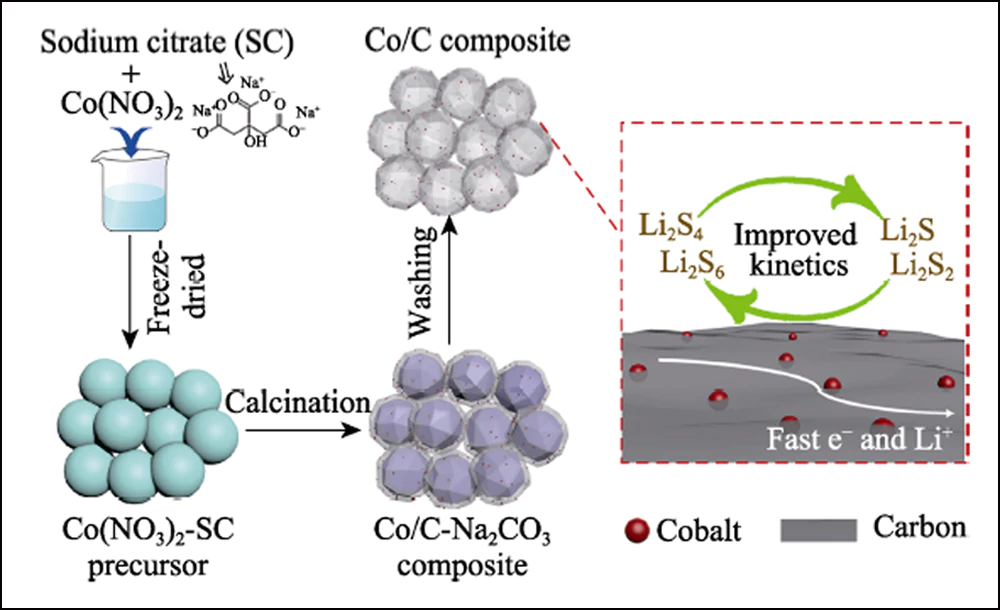
Fig. 1 Schematic illustration for the synthesis steps of hollow Co/C composite and its effect for the resulting electrode
The composition and crystal structure of UWC-700 and Co/C-700 were characterized by XRD. The main diffraction peaks of UWC-700 (Fig. S1) are consistent with monoclinic Na2CO3 (PDF#72-0628), while other three peaks at 2θ=44.2°, 51.5° and 75.9° fit well with crystalline data of Co (PDF#15-0806), indicating the totally decomposition of SC and reduction of cobalt element. The XRD pattern of Co/C-700 (Fig. 2(a)) with only characteristic peaks of cobalt metal suggests the complete removal of Na2CO3. In addition, the obvious broad peak at around 2θ=26° represents the (002) plane of the graphitized carbon. Meanwhile, as shown in the Raman spectra (Fig. 2(b)) of Co/C-700, the intensity ratio for the two obvious bands of D (1382 cm-1) and G (1594 cm-1) is 0.866, responding to its high graphitized degree. In addition, the small peak at 680 cm-1 is the characteristic peak of cobalt. The TGA curve of Co/C-700 is shown in Fig. S2(a) to ensure the Co content. The final product (17.83wt%) after TGA test can be identified as Co3O4 (Fig. S2(b)), and the corresponding Co content in Co/C-700 is 13.09wt% by calculation, which fits well with the XPS result (Fig. 2(c)), the atomic and weight ratios of Co are 3.24at% and 13.66wt%, respectively.
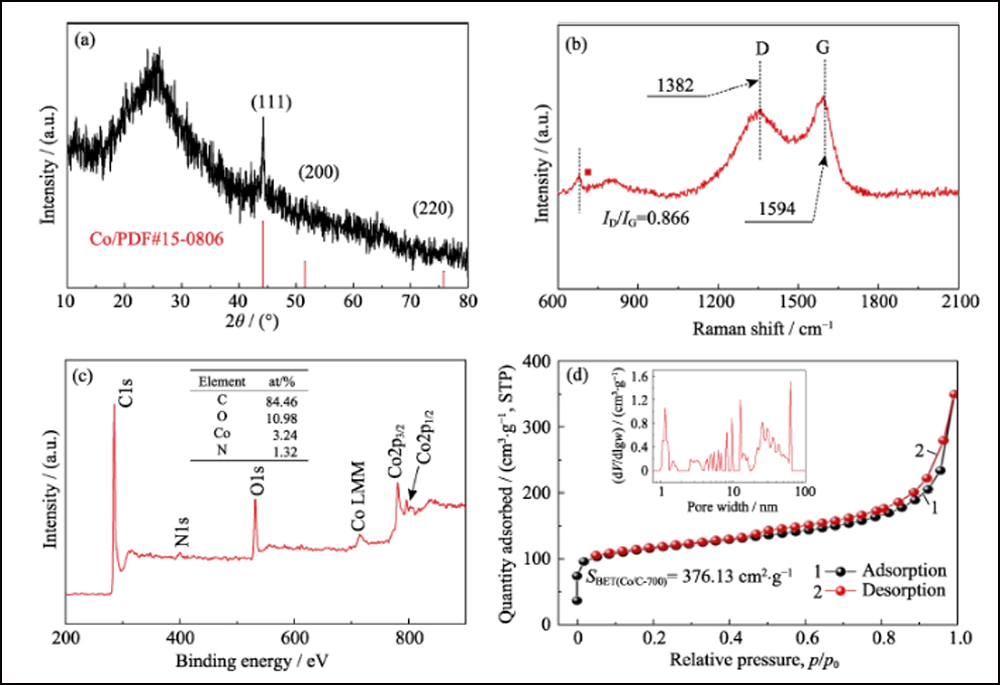
Fig. 2 (a) XRD pattern, (b) Raman spectrum, (c) XPS spectrum and (d) N2 adsorption/desorption isotherm of Co/C-700 with insert in (d) showing pore size distribution
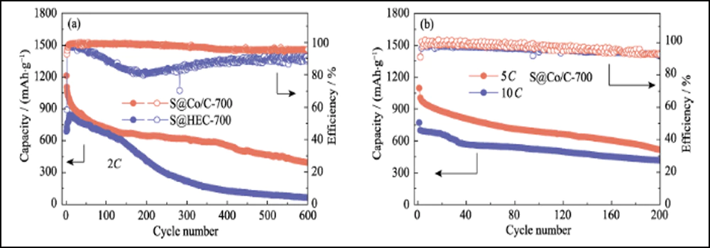
Fig. S1 XRD pattern of UWC-700
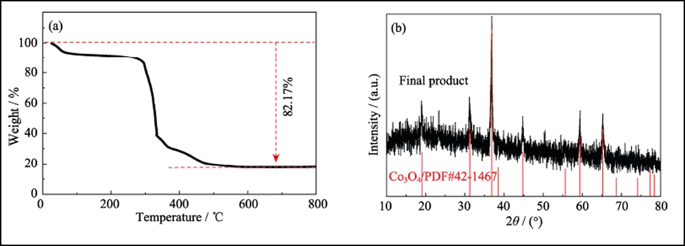
Fig. S2 (a) TGA curve of Co/C-700 in air and (b) XRD pattern of the final product
The porous structure of Co/C was characterized by BET methods. The N2 adsorption-desorption isotherm (Fig. 2(d)) shows a distinct hysteresis loop, representing the abundant mesoporous structure. The specific surface area value and pore volume were measured to be 376.13 m2∙g-1 and 0.52 cm3∙g-1, respectively. The pore size distribution (inset in Fig. 2(d)) determined by the Barrett-Joyner-Halenda (BJH) method shows a distinct hierarchically porous structure with high mesoporosity (62.76%, Table S1). The interconnected mesopore and high surface area can adequately expose the cobalt sites for adsorption and further enhancement of redox reaction. In addition, the same tests were performed with the other two samples, UWC-700 and HEC-700 (Fig. S3). The extremely low surface area (15.09 m2∙g-1) and pore volume (0.026 cm3∙g-1) of UWC-700 show that the majority of the pores are filled with the Na2CO3 crystals. The surface area and pore volume of HEC-700 are almost the same as Co/C-700, which mean the well preservation of carbon framework during the etching steps. In addition, the volume of mesopore in HEC-700 (Table S1) increased by 5.4% after etching, confirming that the Co nanoparticles were in mesoporous size.
The morphology and structure of Co/C-700 were characterized by SEM (Fig. S4) and TEM (Fig. 3(a, b)). The Co/C-700 particles show the structure of 3D interconnected carbon shell. The high-resolution TEM (HRTEM) image (Fig. 3(c)) further shows that the lattice fringes of the nanoparticle with a d-spacing of 0.205 nm corresponds to the (111) plane of metallic cobalt. The d-spacing of crooked fringes wrapping the nanoparticle (0.35 nm) is in good agreement with the (002) plane of graphitic carbon. The EDS mapping images (Fig. 3(d)) show the distribution of Co, C and O elements, confirming that the cobalt element uniformly disperses on the carbon shells.
Table S1 BET surface area and pore volume distribution of UWC-700, Co/C-700 and HEC-700
|
Sample |
SBET/(m2∙g-1) |
Vtotal/(cm3∙g-1) |
Pore volume/% |
||
|
Micro |
Meso |
Macro |
|||
|
UWC-700 |
15.09 |
0.026 |
1.76 |
98.24 |
0 |
|
Co/C-700 |
376.13 |
0.52 |
28.85 |
62.76 |
8.49 |
|
HEC-700 |
369.53 |
0.54 |
25.47 |
68.17 |
6.36 |
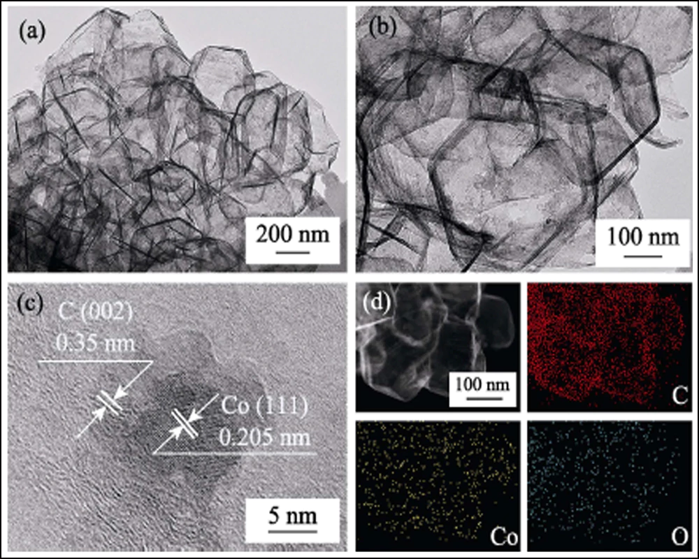
Fig. 3 (a, b) TEM, (c) high-resolution TEM (HRTEM) images and (d) EDS elemental mappings (Co, C and O) of Co/C-700
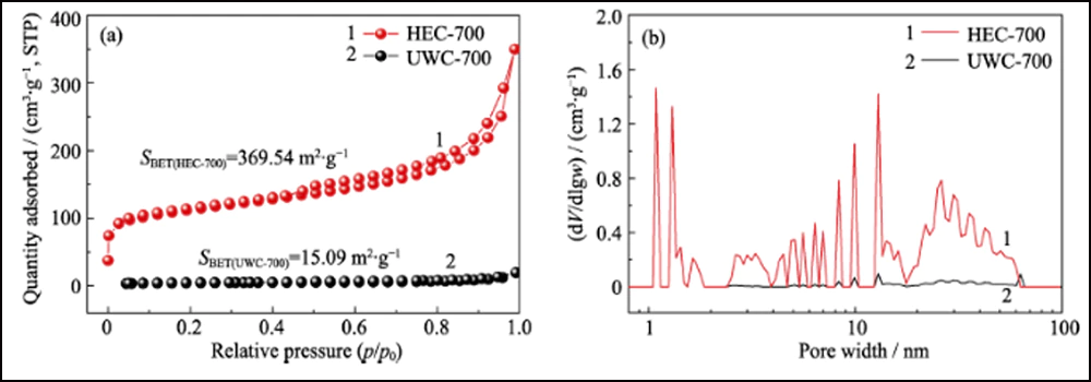
Fig. S3 N2 adsorption/desorption isotherms (a) and pore size distributions (b) of UWC-700 and HEC-700
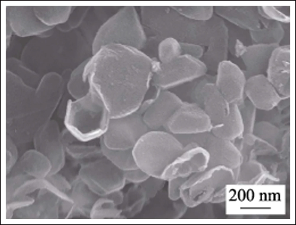
Fig. S4 SEM image of Co/C-700
To further confirm the electrochemical effect of Conanoparticles in Li-S batteries, HEC-700 was employed as the control sample. The XRD pattern, SEM image (Fig. S5) and BET data show that HEC-700 owns almost the same structure as Co/C-700, except the existence of Co element. The S@Co/C-700 and S@HEC-700 electrodes were prepared as the cathodes for Li-S batteries. As shown in Fig. S6, the main weight loss between room temperature and 450 ℃ is attributed to the sublimation of sulfur, corresponding to the sulfur content of 70.99wt% and 68.42wt% in S@Co/C-700 and S@HEC- 700, respectively.
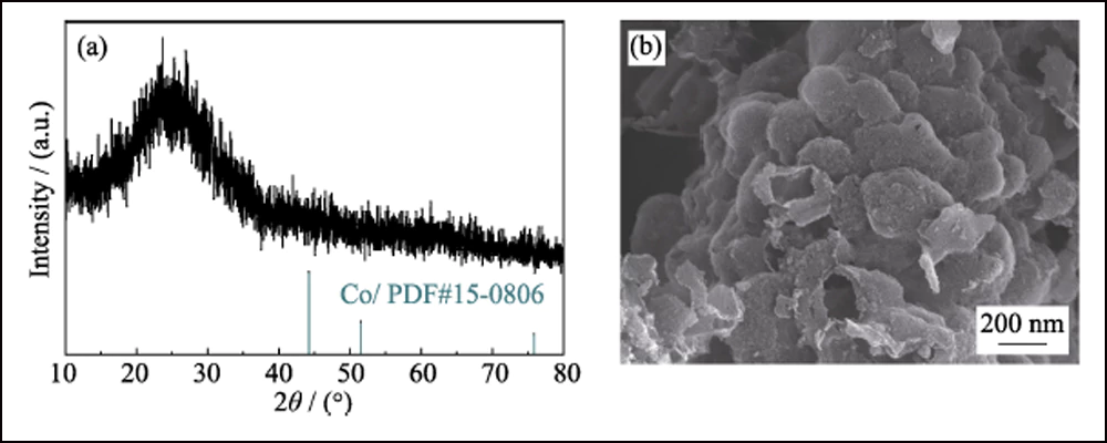
Fig. S5 XRD pattern (a) and SEM image (b) of HEC-700
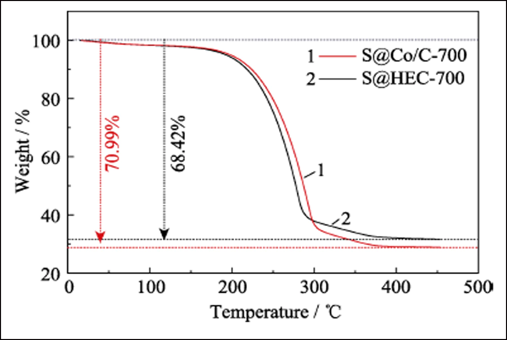
Fig. S6 TGA curves of S@Co/C-700 and S@HEC-700 under N2 atmosphere
The surface composition of S@Co/C-700 was investigated by XPS. The survey spectrum (Fig. S7) shows the presence of S, C, N, O and Co elements on the surface of the composite. The little N is from the precursor of Co(NO3)2. The extremely low ratio of sulfur (7.83at%) indicates that the sulfur crystal has successfully infiltrated into the porous structure. The high- resolution spectrum of S2p (Fig. 4(a)) shows four main peaks. The peaks at 164 and 165.2 eV correspond to the S2p3/2 and S2p1/2, respectively. The peaks located at 169 and 170.1 eV are attributed to thiosulphate and S-Co, respectively. The C1s spectrum is presented in Fig. 4(b). The peaks at 284.8, 285.6 and 288.8 eV correspond to C-C, C-O and O=C-O bonds, almost the same as the C1s spectrum of Co/C-700 (Fig. S8(a)). And the spectrum of O1s (Fig. 4(c)) shows the O=C, O-C and O= C-O at 531.6, 532.4 and 533.4 eV, respectively. When compared with Co/C-700 (Fig. S8(b)), all these peaks shift more than 0.5 eV and further verify the interaction between sulfur and oxygen functional groups. Moreover, the spectrum of Co2p at Fig. 4(d) shows two main peaks of Co2p3/2 and Co2p1/2 at 780.3 and 797.9 eV, which represent for the cobalt metal. Different from the curves of Co/C-700 (Fig. S8(c)), two extra peaks appear at 783.7 and 800.4 eV in S@Co/C-700 which suggest the strong interaction between sulfur and cobalt. The static adsorption test was employed to investigate the interaction between LiPSs and Co/C-700 or HEC-700 more intuitively. And the photograph reveals the colorless solution of Co/C-700 and the almost unchanged color of HEC- 700 (Fig. S9). The obvious difference of two samples further confirms that Co nanoparticles can effectively adsorb LiPSs on the surface and be ready for the further redox reactions.
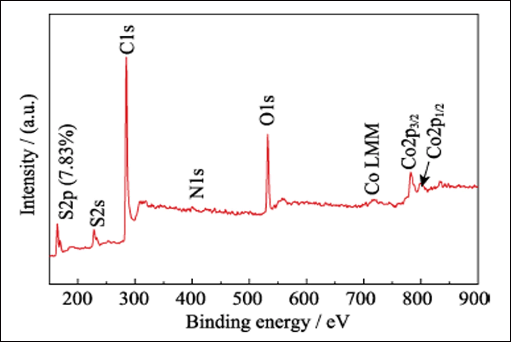
Fig. S7 XPS spectrum of S@Co/C-700 composite

Fig. S8 High resolution XPS spectra of Co/C-700(a) C1s; (b) O1s; (c) Co2p
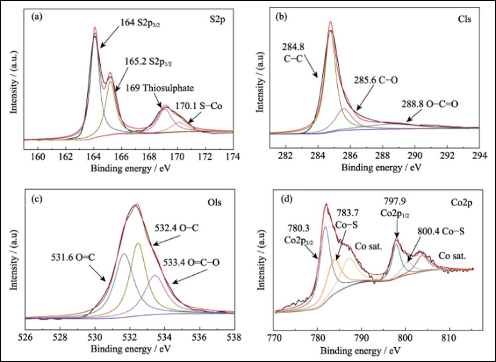
Fig. 4 High resolution XPS spectra for S@Co/C-700 composites
(a) S2p; (b) C1s; (c) O1s; (d) Co2p
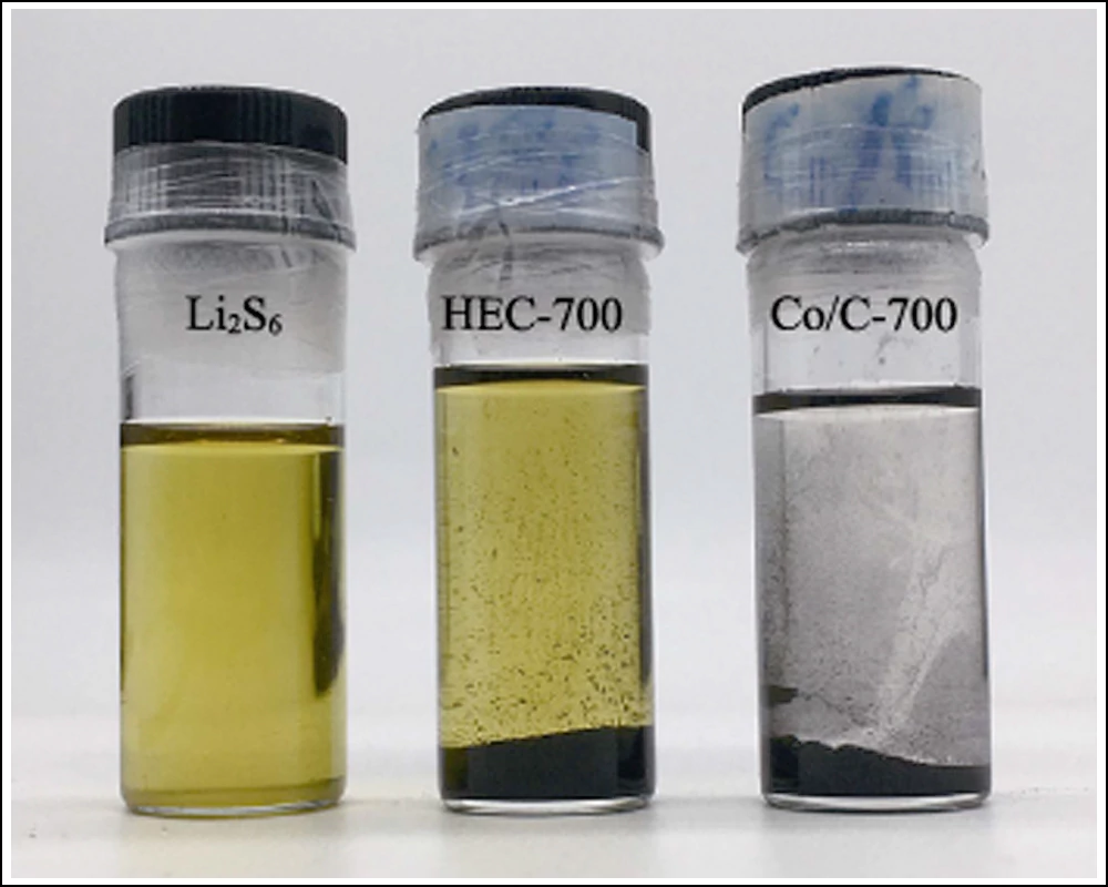
Fig. S9 Photograph of static adsorption test of HEC-700 and Co/C-700 after standing for 1 h
Apart from the effective adsorption and strong interaction, the doping cobalt nanoparticles can efficiently improve the kinetics of conversion reaction between S8 and Li2S. Cyclic voltammetry (CV) of the symmetric cells with Co/C-700 and HEC-700 electrodes were used to confirm the effect of cobalt nanoparticles. The CV curves in Fig. 5(a) clearly reveal eight redox peaks with great superimposition (Fig. S10(a)). The separation and stability of the redox peaks indicate the improved reversibility and kinetics of the conversion reaction. In addition, the curve of the first scan to -1 V reveals three peaks that represent the stepwise reduction from original Li2S6 to insoluble Li2S on the work electrode and oxidation of Li2S6 on the counter electrode. The four peaks at -0.112, 0.093, 0.326 and 0.401 V represent the stepwise oxidation from Li2S to element sulfur on the working electrode. Therefore, the peak at 0.112 V corresponds to the reduction from S8 to Li2S6. In addition, the peaks with good sustainability under higher scan rates (Fig. S10(b)) also indicate the efficient electrochemical process based on the Co/C-700 electrodes. In contrast, the experimental control of HEC-700 electrodes show only two pairs of broad peaks (Fig. 5(b)) with the cyclic drifting (Fig. S10(c)), and the inconspicuous peaks at -0.264/0.264 V become invisible under higher rates (Fig. S10(d)), indicating the sluggish kinetics and incomplete conversion of the polysulfides reaction without the existence of Co nanoparticles.
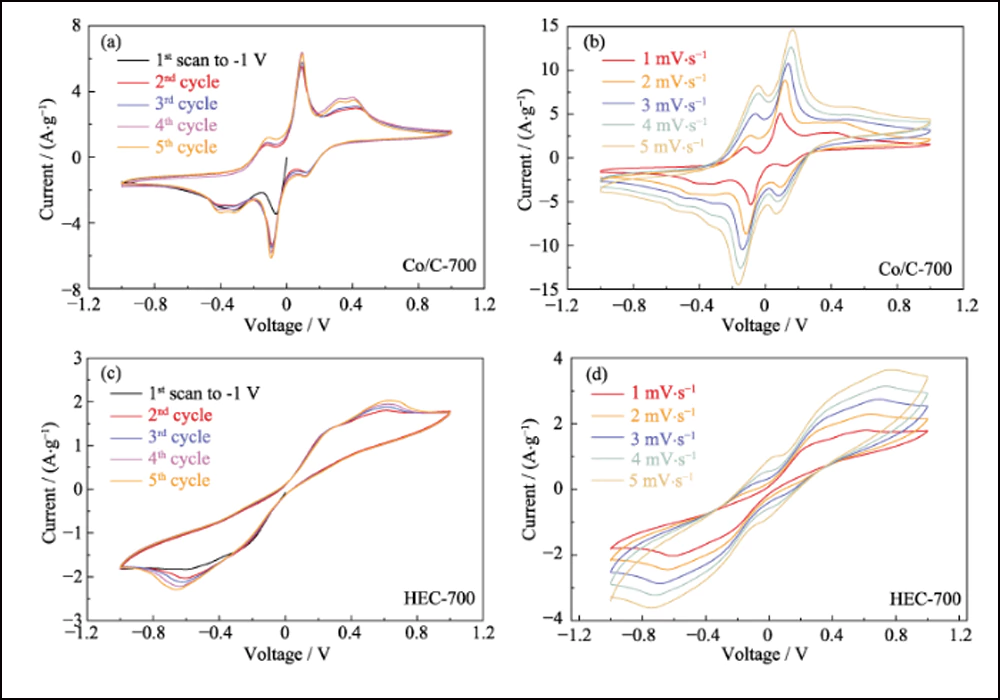
Fig. S10 Multi-cycle CV curves of Co/C-700 based symmetric cells at 1 mV∙s-1 (a) and increased rates (b), and multi-cycle CV curves of HEC-700 at 1 mV∙s-1 (c) and increased rates (d)
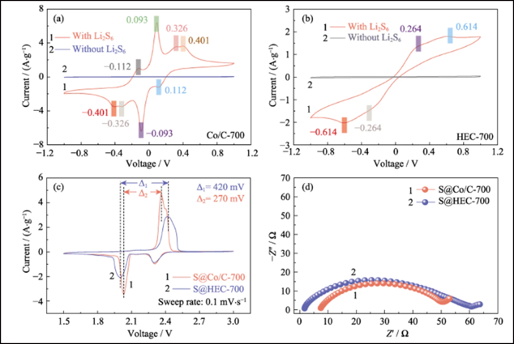
Fig. 5 CV curves of (a) Co/C-700 and (b) HEC-700 based symmetric cells with and without 0.2 mol∙L-1 Li2S6 at 1 mV∙s-1; (c) CV curves and (d) EIS plots of S@Co/C-700 and S@HEC-700 electrodes
To further confirm the enhanced electrochemical kinetics in the presence of cobalt nanoparticles, the CV tests of S@Co/C-700 and S@HEC-700 electrodes (Fig. 5(c)) were measured at a scan rate of 0.1 mV∙s-1. For the cathodic reduction process of S@Co/C-700, two reversible peaks at 2.306 and 2.031 V are associated with the transformation from sulfur to soluble LiPSs and further reduction to insoluble Li2S2/Li2S, respectively. In comparation, the latter reduction peak of S@HEC-700 shows a significant negative shift. It suggests the more sluggish reaction kinetics, which may increase the detention time of LiPSs and aggravate the shuttling effect. For the anodic process, the oxidation process of S@Co/C-700 reveals an unobtrusive peak at 2.397 V and a major peak at 2.361 V, corresponding to the oxidation from Li2S2/Li2S to LiPSs and further to sulfur, respectively. The separation of the oxidation peaks shows the enhanced kinetics of the former reaction. Furthermore, the interval between the second reduction peak and the major oxidation peak of S@Co/C-700 (270 mV, Fig. 5(c)) is significantly smaller than that of S@HEC-700 (420 mV), indicating the reduced polarization overpotential and improved kinetics of redox reaction with the existence of cobalt. The EIS curves (Fig. 5(d)) show smaller charge- transfer resistance (the size of high-frequency semicircle) of S@Co/C-700 electrode (43.1 Ω) than that of S@HEC-700 (58.7 Ω), which also reveals the enhanced reaction kinetics by cobalt.
Fig. 6 compares the electrochemical performance of the S@Co/C-700 and S@HEC-700 cathodes. The rate capabilities of S@Co/C-700 (Fig. 6(a)) show a much higher initial discharge capacity (1280 mAh∙g-1) than S@HEC-700 (847 mAh∙g-1) at the current rate of 0.5C (1C = 1672 mAh∙g-1). At higher cycling rates of 1C, 2C, 5C and 10C, the discharge capacities of S@Co/C-700 cathode reach 1058, 948, 867 and 797 mAh∙g-1, and further recover to 968 mAh∙g-1 at 1C (95 % of the 10th cycle). And the galvanostatic charge-discharge voltage profiles at different rates show that the S@Co/C-700 electrode exerts smaller overpotential and much longer discharge plateau even at 10C (Fig. S11). The cycle stabilities of the two cathodes at 1C rate are compared in Fig. 6(b). The S@Co/C-700 cathode shows a high initial capacity of 1244 mAh∙g-1, and maintains 770 mAh∙g-1 after 200 cycles with high Coulomb efficiency (higher than 96 %), revealing much higher capacity and better stability than the S@HEC-700. The long-term cycling performances at 2C exhibited in Fig. S12(a). After 600 cycles, the S@Co/C-700 cathode maintained a discharge capacity of 401.7 mAh∙g-1 (65.3 mAh∙g-1 for S@HEC-700). The extremely high rates at 5C and 10C are further evaluated for the S@Co/C-700 cathode (Fig. S12(b)). It shows high initial discharge capacities (1098 and 772 mAh∙g-1 at 5C and 10C, respectively) without any activation step and stable cycling performance (518 and 416 mAh∙g-1 at 5C and 10C, respectively) for more than 200 cycles. The more excellent cycle stability and rate performance of S@Co/C-700 electrode is attributted to the benefits of cobalt nanoparticles.

Fig. 6 (a) Rate capabilities at various rates from 0.5C to 10C and (b) cycling stabilities at 1C for S@Co/C-700 and S@HEC-700 electrodes
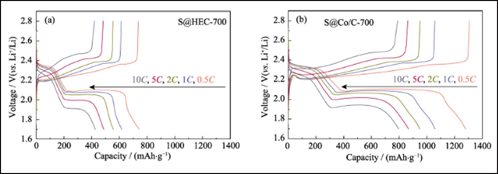
Fig. S11 Voltage profiles of S@HEC-700 (a) and S@Co/C-700 (b) electrodes at various rates from 0.5C to 10C
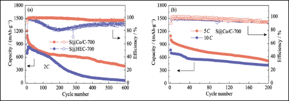
Fig. S12 (a) Cycling stabilities of S@Co/C-700 and S@HEC-700 electrodes at 2C; (b) Cycling performance of S@Co/C-700 at 5C and 10C
3 Conclusion
In summary, we design a large-scale synthesis of Co/C-700 composites as the host material to support sulfur for Li-S batteries. Combining with the results of CV and EIS, we conclude that the embedded Co nanoparticles decrease the overpotential and promote the conversion kinetics of LiPSs. Furthermore, the XPS and static adsorption test show the strong interaction between LiPSs and the doped Co. With the cooperation of Co and the unique hollow porous structure, the obtained S@Co/C-700 cathodes exhibit high specific capacity of 1280 mAh∙g-1 at 0.5C, and stable long cycle performance from 1C to 10C. This work demonstrates the feasibility of high energy density Li-S batteries with the dopant of cobalt metal for high-rate requirements.
Supporting materials
Cobalt-doped Hollow Carbon Framework as Sulfur Host for the Cathode of Lithium Sulfur Battery
JIN Gaoyao, HE Haichuan, WU Jie, ZHANG Mengyuan, LI Yajuan, LIU Younian
Hunan Provincial Key Laboratory of Micro & Nano Materials Interface Science, College of Chemistry and Chemical Engineering, Central South University, Changsha 410083, China
Materials characterization
The crystalline structures of the as-synthesized samples were characterized by X-ray power diffraction (XRD, Dmax/2550VB, Rigaku, Japan) with Cu Kα radiation. The surface morphology and microstructure were obtained by a scanning electron microscopy (SEM, FEI Verios 460). Transmission electron microscopy (TEM, JEM-2100F) equipped with an X-ray energy dispersive spectrometer (EDS) was used to collect transmission and high-resolution images of the Co/C-700. The Co content in Co/C-700 and S content in S@Co/C- 700 or S@HEC-700 were determined by thermogravimetric analyzer (TGA, Q600, USA) in air or N2, respectively, with a heating rate of 10 ℃∙min-1. Raman spectroscopy was performed using a reflex Raman system (Renishaw in Via Raman microscope, UK) equipped with a microscope under 532 nm laser radiation at 50 mW. X-ray photoelectron spectrometer (XPS) analysis was performed at an ESCALAB 250XI X-ray photoelectron spectrometer (Thermo Fisher Scientific, USA). The specific surface area and pore size distribution of samples were determined by nitrogen adsorption- desorption analysis.
Static adsorption of polysulfides
Typically, 0.003 mol/L Li2S6 solution was obtained by reacting stoichiometric Li2S and S in 1,2-dimethoxyethane(DME) and 1,3-dioxolane(DOL) (1 : 1 in volume) at 60 ℃ for 24 h. Then, 10 mg Co/C-700 or HEC-700 was added into 3 mL of the lithium polysulfide solution. The photograph was taken after the sample stood for 1 h.