
Categories
new blog
- Solid-State Battery Manufacturing Equipment Guide 2026–2027
- Supercapacitors vs Batteries: Complementary Industrial Energy Storage
- Battery Electrolyte Selection Guide: What Procurement Managers Must Know
- Coin Cell Lab Equipment: The Complete Checklist for Battery R&D Labs
- Battery Cathode Materials Compared: NMC vs LFP vs NCA
Tags
Ultra-high Nickel LiNi0.91Co0.06Al0.03O2@Ca3(PO4)2 Cathode Materials
Enhanced Lithium Storage Stability Mechanism of Ultra-high Nickel LiNi0.91Co0.06Al0.03O2@Ca3(PO4)2 Cathode Materials
Author:ZHU Hezhen, WANG Xuanpeng, HAN Kang, YANG Chen, WAN Ruizhe, WU Liming, MAI Liqiang. Enhanced Lithium Storage Stability Mechanism of Ultra-high Nickel LiNi0.91Co0.06Al0.03O2@Ca3(PO4)2 Cathode Materials. Journal of Inorganic Materials, 2022, 37(9): 1030-1036 DOI:10.15541/jim20210769
Ultra-high nickel material as a new lithium-ion battery cathode has attracted much attention due to its high specific capacity, high voltage and low cost. However, the generated microcracks, mechanical pulverization and irreversible phase transformation during cycling, result in poor cycling stability. Herein, a series of Ca3(PO4)2- coated ultra-high nickel LiNi0.91Co0.06Al0.03O2 materials with different thicknesses (NCA@nCP) were prepared through a facile wet-chemistry strategy. Among them, NCA@1CP manifested specific discharge capacity of 204.8 mAh/g under 2.7-4.3 V at 1C (1C=200 mA/g), with a capacity retention rate of 91.5% after 100 cycles. Even after 300 cycles at 2C, the specific discharge capacity retained 153.4 mAh/g. Material characterization results further confirm that the coating shell inhibits the Li/Ni mixing, irreversible phase transformation and mechanical pulverization of the NCA@1CP, greatly improving the cycling stability. This work shows that the Ca3(PO4)2 coating strategy has great application potential in improving the lithium storage stability of ultra-high nickel cathode materials.
In order to meet the demand for high energy density of lithium-ion batteries, researchers have made a series of progress in the field of developing cathode materials with high reversible specific capacity and high operating voltage. Ultra-high nickel cathode materials such as LiNixM1-xO2 (M is a transition metal, x≥0.9) have the advantages of high capacity, high voltage and low cost, and are an important development direction of cathode materials for high energy density lithium-ion batteries in the future. Kim synthesized LiNi0.90Co0.05Mn0.05O2 ultra-high nickel material by co-precipitation method, and the initial discharge specific capacity of Li-ion battery using it as cathode material was 229.0 mAh/g. The LiNi0.90Co0.09W0.01O2 synthesized by Ryu exhibited an ultra-high initial discharge specific capacity of 231.2 mAh/g. However, the capacity fading problem limits the commercial application of this type of materials, and a large number of studies have proved that the reasons can be attributed to the following three aspects: (1) High Ni content will aggravate Li/Ni mixing, inhibit lithium ion diffusion and increase reaction impedance, resulting in actual capacity loss. (2) The highly active Ni4+ formed under the condition of lithium removal is easy to have side reaction with the electrolyte and consume the electrode and electrolyte. It promotes the structural transformation of the material from the layered phase to the disordered spinel phase and the rock-salt phase and severely damages the crystal structure of the material, reducing the cycling stability. (3) The internal mechanical stress formed by the sudden shrinkage of the lattice parameter c induced by the H2-H3 phase transition leads to the generation and expansion of microcracks, and the electrolyte diffuses into the interior of the material particles, thereby eroding the electrode material and aggravating the performance degradation.
Coating modification is widely used to solve the capacity fading problem of high-nickel cathode materials and improve the cycling stability, among which oxide materials are the most common, such as Al2O3, TiO2, SiO2, and ZrO2. Compared with oxides, phosphates have better lithium ion mobility and chemical stability, and have received extensive attention in the field of surface modification of high-nickel cathode materials in recent years. Xiao(XIAO Y H, MIARA L J, WANG Y, et al.) confirmed through computational screening that phosphate as a cathode coating material can significantly improve the stability. Common phosphate coating agents are Mn3(PO4)2, BPO4, AlPO4 and Li3PO4. Yan(YAN P F, ZHENG J M, LIU J, et al.) used atomic layer deposition technology to coat Li3PO4 on the surface of high-nickel cathode material LiNi0.76Mn0.14Co0.10O2, which suppressed the irreversible phase transition of the material and improved the kinetics of the cathode-electrolyte interface. Feng(FENG Z, RAJAGOPALAN R, SUN D, et al.) coated Li3PO4-AlPO4-Al(PO3)3 on LiNi0.8Co0.1Mn0.1O2 material, and the cycle performance was significantly improved. Among phosphate materials, Ca3(PO4)2(CP) has excellent chemical and thermal stability due to the strong bond between Ca2+ and [PO4]3-. However, the ultra-high nickel cathode materials modified by CP coating have not been reported yet. Therefore, a series of CP coated ultra-high nickel LiNi0.91Co0.06Al0.03O2 cathode materials (NCA@nCP, n=0.5, 1, 3) were prepared by a simple wet chemical method. The structure, morphology and electrochemical performance improvement mechanism of NCA@nCP were studied and analyzed in detail.
Preparation of cathode material
Ni0.91Co0.06Al0.03(OH)2 and LiOH·H2O were mixed at a molar ratio of 1:1.05, then heated to 500 °C for 5 h at a rate of 5 °C/min in an oxygen atmosphere, and then heated to 720 °C for insulation After 15 h, and finally cooled to room temperature naturally, black NCA powder was obtained. Weigh 0.74 g of NH4H2PO4 and 2.28 g of Ca(NO3)2·4H2O and dissolve them in 100.0 mL of water and 100.0 mL of anhydrous ethanol, respectively. First, 0.5 mL of Ca(NO3)2 solution (solution A) and 0.5 mL of NH4H2PO4 solution (solution B) were added to 50.0 mL of absolute ethanol, then 1.00 g of NCA powder was slowly added, and finally the solvent was removed by stirring and evaporation at 80 °C to obtain powder. Then, the powder was sintered in an oxygen atmosphere at 550 °C (heating rate of 5 °C/min) for 2 h. At this time, the mass fraction of CP was 0.5%, and the obtained product was defined as NCA@0.5CP. When each of the A and B solutions is 1.0 mL, the mass fraction of CP is 1.0%, and the obtained product is defined as NCA@1CP; when the A and B solutions are each 3.0 mL, the mass fraction of CP is 3.0%, and the obtained product is defined as NCA@3CP.
Material Characterization
The crystal structure of the material was characterized by X-ray diffraction (X-ray diffraction, XRD, D8 Discover X, CuKα radiation). The refined XRD data were calculated by GSAS software using the Rietveld method. The morphology and microstructure of the materials were characterized by scanning electron microscopy (SEM, JEOL JSM-7100F) and transmission electron microscopy (TEM, JEM-2100F). The element distribution of the material was observed by X-ray energy dispersive spectrometer (Energy dispersive spectrometer, EDS, EDX-GENESIS 60S). X-ray photoelectron spectroscopy (X-ray photoelectron spectroscopy, XPS, VG MultiLab 2000) was used to analyze the composition and valence of elements on the surface of the material.
Electrochemical testing
The active cathode material, Super-P, and polyvinylidene fluoride were mixed in a mass ratio of 8:1:1, dispersed in N-Methyl-2-pyrrolidone (NMP), and magnetically stirred for 12 h, a uniform slurry was formed, coated on aluminum foil, and finally dried in a vacuum oven at 120 °C for 12 h to remove NMP. Cut the aluminum foil into a positive electrode sheet with a diameter of 10 mm, and the mass load of the cut positive electrode sheet is 2~3 mg/cm2. Lithium metal sheets (or graphite) and porous polypropylene membranes (Celgard 2500) were used as the counter electrode and separator for half cells (or full cells), respectively. The electrolytes used in the half-cell and full-cell are 1 mol/L LiPF6 solutions dissolved in ethylene carbonate/ethyl methyl carbonate/diethyl carbonate (volume ratio 1:1:1). Assemble CR2016 coin cells in an argon glove box. Electrochemical charging/discharging experiments were performed at 2.7-4.3V and 2.7-4.5V intervals using a battery test system. using an electrochemical workstation to test Cyclic voltammetry (CV) at 0.1 mV/s and 2.7-4.3 V.
Results and discussion
Figure 1(a) shows the XRD patterns of NCA and NCA@nCP materials. The XRD patterns of all materials show similar peak positions and peak shapes, and no other impurity peaks. In addition, the (006)/(102) and (108)/(110) diffraction peaks of the material after coating and before coating were obviously split, indicating that the CP coating did not change the original layered structure of the NCA material. In such nickel-based materials, since the ionic radius (0.069 nm) of Ni2+ is similar to that of Li+ (0.076 nm), it is easy to migrate to the lithium layer, resulting in the mixed arrangement of Li/Ni, and the ratio of I(003)/I(104) can be Reveal the Li/Ni mixing phenomenon of the material. The results show that when I(003)/I(104) is greater than 1.2, the nickel-based material is usually regarded as having a well-ordered layered structure, and the larger I(003)/I(104) is, the smaller is the degree of Li/Ni mixing. As shown in Table S1, the I(003)/I(104) of both NCA and NCA@nCP materials are greater than 1.2, of which NCA@1CP is the highest (2.261), which is greater than NCA (1.426), indicating that the CP coating inhibits the Li of NCA. /Ni mixed arrangement. Figure 1(b) and Figure S1 are the refined XRD results of NCA@1CP and NCA and NCP@nCP, respectively. All diffraction peaks belong to the hexagonal O3-type layered structure. The difference in lattice parameters between NCA and NCA@nCP is small, indicating that the CP does not enter the lattice of the NCA material (Table S2), the error factors (Rp and Rwp) of the refinement are low, and the fitting reliability is high.
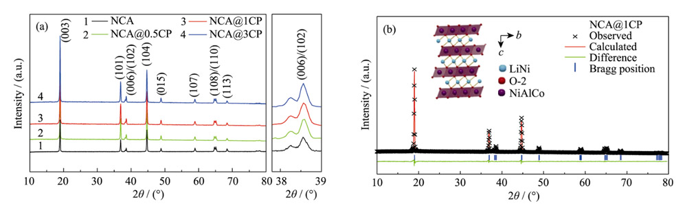
Fig. 1 (a) XRD patterns of NCA and NCA@nCP (n=0.5, 1, 3), and (b) Rietveld refinement results of NCA@1CP
Figure 2(a) and Figure S2 are the SEM characterization results of NCA@1CP and NCA and NCP@nCP materials, respectively. The morphology of all materials is spherical, and the spherical morphology of the materials does not change after CP coating. TEM characterization results show that the NCA material exhibits good crystallinity with a lattice fringe spacing of 0.47 nm, which corresponds to the (003) crystal plane of NCA (Fig. 2(b)). In contrast, an amorphous cladding layer with a thickness of about 5 nm was clearly observed on the surface of the NCA@1CP material (Fig. 2(c)), indicating that the CP was effectively coated on the surface of the NCA material. The element distribution of NCA@1CP and NCA materials was analyzed by EDS (Figure 2(d) and Figure S3), and Ca and P elements were uniformly distributed on the surface of spherical morphology of NCA@1CP materials, while only Ni, Co and Al elements could be detected in NCA materials.
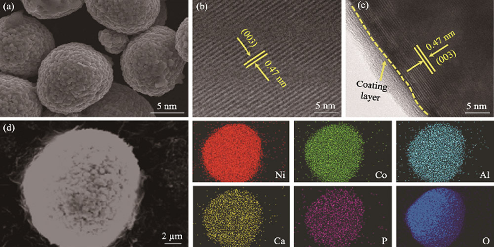
Fig. 2 (a) SEM image of NCA@1CP, high-resolution TEM images of (b) NCA and (c) NCA@1CP, and (d) EDS elemental mappings of NCA@1CP
The composition and valence state of elements on the surface of the materials were determined by XPS analysis of NCA and NCA@1CP materials. As shown in Figure 3(a), four elements of Ni, Co, Al and O are detected in NCA, while in addition to the above four elements, Ca and P elements are also detected in NCA@1CP, which proves that CP is successfully coated on the surface of NCA material. As shown in FIG.3 (b), the two peaks at 856.5 and 873.3 eV belong to Ni2p3/2 and Ni2p1/2, respectively. The Ni2p3/2 peak can be further fitted to two sub-peaks at 854.7 and 855.8 eV, corresponding to bivalent and trivalent Ni, respectively. The peak area of divalent Ni in NCA@1CP material is smaller than that in NCA material, indicating that CP coating modification reduces the content of divalent Ni in NCA, and to a certain extent, it can inhibit Li/Ni mixing. The two peaks at 795.5 and 779.9 eV belong to Co2p1/2 and Co2p3/2, respectively, indicating that Co is trivalent (Figure 3(c)), while the Al2p3/2 peak at 73.1 eV matches well with the trivalent Al peak (Figure 3(d)). In addition, the peaks at 133.4 eV corresponding to P2p (Figure 3(e)) and 347.0 and 350.6 eV corresponding to Ca2p3/2 and Ca2p1/2 (Figure 3(f)) were detected on the NCA@1CP material surface, while no peaks of P and Ca were detected in the NCA material.
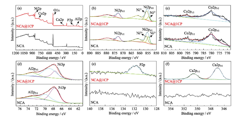
Fig. 3 (a) Full survey, (b) Ni2p, (c) Co2p, (d) Al2p, (e) P2p and (f) Ca2p XPS spectra for NCA and NCA@1CP
In Figure 4(a, b) and Figure S4, the CV curves of the first three turns of lithium ion half-cell assembled with NCA and NCA@nCP materials as positive electrodes show that there are three pairs of different REDOX peaks in the test interval of 2.7-4.3V, corresponding to different phase transition processes: In the process of Li+ extraction, the oxidation peak at 3.83V represents the transition from hexagonal phase to monoclinic phase (H1-M), and the oxidation peaks at 4.01 and 4.20V represent the transition from monoclinic phase to hexagonal phase (M-H2) and the transition from hexagonal phase to hexagonal phase (H2-H3), respectively. The reduction peaks of Li+ embedding process are 3.64 V, 3.96 V and 4.15 V, respectively. The potential difference between the oxidation peak and the reduction peak during the cycle can reflect the electrochemical kinetics of the material. The potential difference of the initial REDOX peak of NCA is 0.185 V, which is larger than that of NCA@0.5CP(0.154 V), NCA@1CP(0.112 V) and NCA@3CP(0.143 V) after coating. The polarization of NCA@1CP material is the least during electrochemical lithium incalation/lithium removal. FIG. 4(c) shows the initial charge and discharge curves of lithium ion half-cell assembled with NCA and NCA@nCP material as positive electrode at 0.2C(1C=200 mA/g) and 2.7-4.3V. The initial discharge capacity of NCA is 212.4 mAh/g, while that of NCA@nCP(n=0.5, 1, 3) is 211.1, 210.4 and 203.3 mAh/g, respectively. Figure 4(d) shows the half-cell cycle performance of NCA and NCA@nCP material at 1C and 2.7-4.3V. In order to make the electrode material fully activated, the battery was first charged and discharged at 0.2C for 2 cycles, NCA@1CP at 1C discharge specific capacity of 204.8 mAh/g, 100 cycles after 187.5 mAh/g, the corresponding capacity retention rate is 91.5%. However, the specific capacity of NCA is 203.2 mAh/g at 1C, and only 168.0 mAh/g after 100 cycles (capacity retention rate is 82.6%). The above results indicate that the NCA@1CP material exhibits excellent cycling stability at both low and high cut-off voltages. Figure 4(f) shows the long cycle performance of NCA and NCA@1CP material at 2C and 2.7-4.3V. The initial discharge capacity of NCA@1CP is 184.9 mAh/g, and 153.4 mAh/g remains after 300 cycles, which is 82.9% of the initial value. However, the initial discharge specific capacity of NCA at 2C is 173.5 mAh/g, and only 115.3 mAh/g after 300 cycles, which is only 66.4% of the initial value. Figure S5(a~c) shows the rate performance of NCA and NCA@nCP materials in the range of 2.7~ 4.3V. The rate performance of NCA is poor, especially the specific capacity of 105.1 mAh/g at 10C ultra-high rate. In contrast, NCA@1CP has a discharge specific capacity of up to 130.4 mAh/g at 10C, showing excellent rate performance.
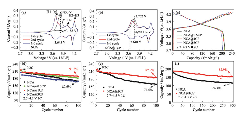
Fig. 4 CV curves for (a) NCA and (b) NCA@1CP; (c) Initial charge-discharge curves under 2.7-4.3 V at 0.2C and (d) cycling properties under 2.7-4.3 V at 1C for NCA and NCA@nCP; Cycling properties for NCA and NCA@1CP (e) under 2.7-4.5 V at 1C and (f) under 2.7-4.3 V at 2C
The crystal structure evolution of NCA and NCA@1CP materials during charge-discharge cycling was monitored in real time by in situ XRD (Fig. 5). As shown in Fig. 5(a, b), during the first cycle of charging to 4.1 V, the crystal transitions from H1 phase to H2 phase, the (003) diffraction peak shifts to a low angle, and the lattice parameter c gradually increases. This phenomenon can be attributed to the extraction of lithium ions from the lattice, the enhanced electrostatic repulsion between the transition metal layers, and the larger interlayer spacing. After further charging, the crystal changes from the H2 phase to the H3 phase, resulting in a sharp shift of the (003) diffraction peak to a high angle, and a sharp contraction of the lattice parameter c. This can be attributed to: (1) The covalent nature of the Ni4+-O2- bond in the transition metal layer is enhanced, the electrostatic repulsion between the transition metal layers is weakened, and the interlayer spacing is significantly smaller. (2) The continuous extraction of lithium ions between transition metal layers weakens the support effect and reduces the interlayer spacing. The maximum angular shift of the (003) diffraction peak of the NCA material during the H2-H3 phase transition is 0.76° (Fig. 5(e)). Although the NCA@1CP material also exhibits the H2-H3 phase transition process (Fig. 5(c, d)). However, the maximum angular shift of the (003) diffraction peak is only 0.57° (Fig. 5(f)). Figure 5(g) shows the evolution curves of lattice parameter c during delithiation of NCA and NCA@1CP materials. The shrinkage of the lattice parameter c of NCA@1CP (3.5%) is smaller than that of NCA (4.1%). It is revealed that NCA@1CP has better structural stability. In situ XRD results show that the CP coating can suppress the H2-H3 irreversible phase transition of the NCA material, thereby improving the electrochemical performance of the material.
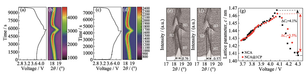
Fig. 5 Voltage-time variation curves during in-situ XRD for (a) NCA and (c) NCA@1CP; In-situ XRD patterns for (b, e) NCA and (d, f) NCA@1CP; (g) Variation curves of the lattice parameter c during charging for NCA and NCA@1CP
In order to comprehensively evaluate the effect of CP coating on the morphology and microstructure of materials during the electrochemical process, the pole pieces of NCA and NCA@1CP half-cells after 100 charge-discharge cycles (1C, 2.7~4.3 V) were characterized. The SEM characterization results showed that only a few microcracks appeared on the surface of the NCA@1CP material, while a large number of cracks appeared on the surface of the NCA material and some particles had been pulverized (Fig. S6(a, b)). It shows that the CP coating layer inhibits the surface microcracks and mechanical powdering of the material to a certain extent. Figure S6(c–f) shows the XRD patterns of NCA and NCA@1CP materials before and after 100 cycles. The (006) and (102) diffraction peaks of NCA overlap after 100 cycles (Fig. S6(d)), while the (006) and (102) diffraction peaks of NCA@1CP are still split after 100 cycles (Fig. S6(f)) ). It shows that the CP coating layer can improve the stability of the NCA structure. To further verify the lithium storage stability of NCA@1CP, a coin-type full battery was assembled with NCA and NCA@1CP materials as the positive electrode and graphite as the negative electrode, respectively (Fig. 6). At 1C (1C=200 mA/g) and 2.7~4.25 V, the initial discharge specific capacity of the NCA@1CP full cell is 201.4 mAh/g. After 70 cycles, the discharge specific capacity maintained 84.6% of the initial value (Fig. 6(a)). However, the initial discharge specific capacity of the NCA full cell is 198.6 mAh/g, and the discharge specific capacity after 70 cycles is only 65.6% of the initial value. The average discharge plateau in the second cycle of the NCA@1CP full cell is 3.72 V (Fig. 6(b)), and the calculated energy density based on the active mass of the cathode and anode materials is as high as 442 Wh/kg.
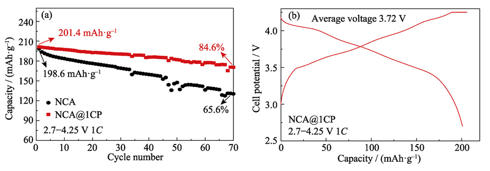
Fig. 6 (a) Cycling properties of full cells both NCA and NCA@1CP as cathode, graphite as anode under 2.7-4.25 V at 1C, and (b) charge-discharge curves of the second cycle for NCA@1CP in full cell
Conclusion
In this study, NCA@1CP cathode materials were prepared by a facile wet-chemical strategy, which significantly improved the electrochemical lithium storage stability of NCA materials. The NCA@1CP material exhibits a capacity retention rate of 91.5% after 100 cycles at 1C, showing an ultra-long cycle life of over 300 cycles even at a high rate of 2C.
The CP coating significantly prolongs the cycle life of NCA cathode materials, mainly due to the following aspects:
(1) The introduction of the CP coating layer reduces the degree of Li/Ni mixed arrangement.
(2) The CP coating relieves the shrinkage of lattice parameter c and suppresses the irreversible phase transition of H2-H3.
(3) The CP coating layer inhibits the microcracks and mechanical pulverization of the material surface.
This study shows that the CP coating layer has great application potential in the surface modification of ultra-high nickel cathode materials to improve the stability of lithium storage, and provides a new idea for the optimization strategy of electrochemical stability of ultra-high nickel cathode materials.
Supplementary Material
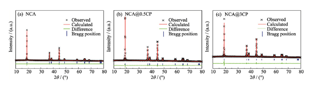
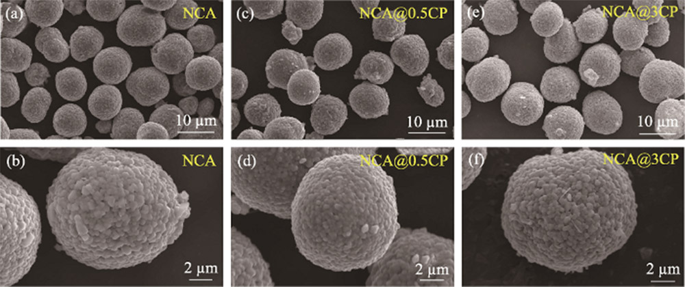
Fig. S2 SEM images of (a, b) NCA, (c, d) NCA@0.5CP and (e, f) NCA@3CP
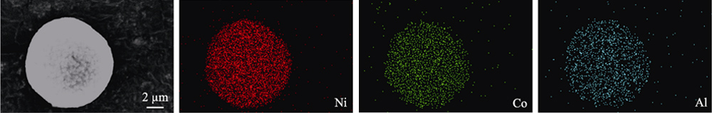
Fig. S3 EDS elemental mappings of NCA
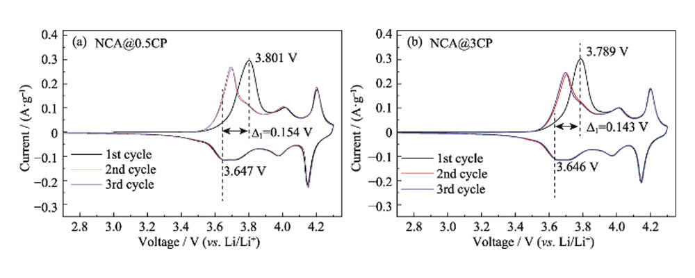
Fig. S4 CV curves for (a) NCA@0.5CP and (b)NCA@3CP
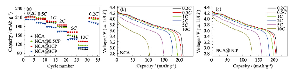
Fig. S5 (a) Rate performance for NCA, NCA@0.5CP, NCA@1CP and NCA@3CP; Corresponding discharge curves during rate tests of (b) NCA and (c) NCA@1CP
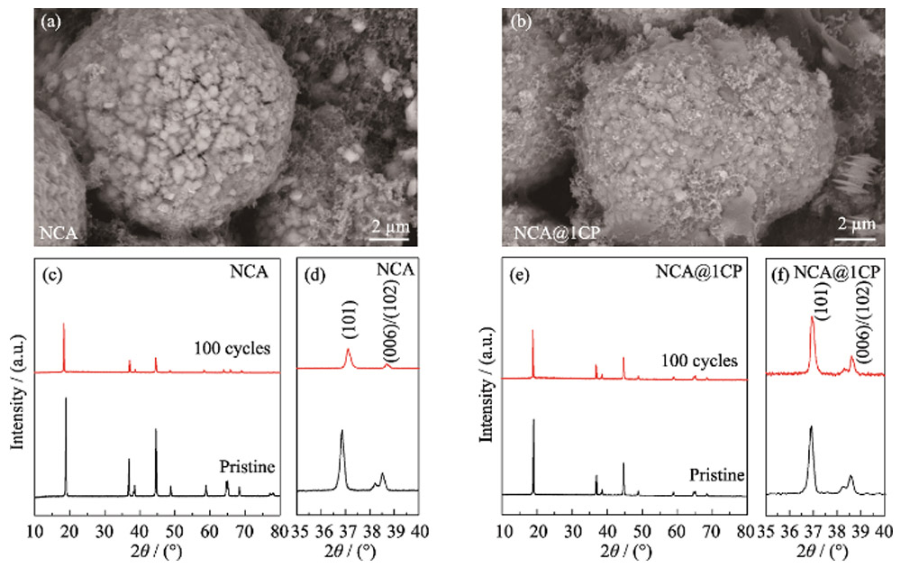
Fig. S6 (a, b) SEM images and (c-f) XRD patterns of NCA and NCA@1CP after 100 cycles under 2.7-4.3 V at 1C
|
Sample |
NCA |
NCA@0.5CP |
NCA@1CP |
NCA@3CP |
|
I(003)/I(104) |
1.426 |
2.120 |
2.261 |
1.981 |
Table S2 Lattice parameters of the NCA, NCA@0.5CP, NCA@1CP and NCA@3CP calculated from XRD Rietveld refinement
| Sample | a/nm | c/nm | V/nm3 | c/a | Rwp | Rp |
| NCA | 0.287398 | 1.421071 | 0.101652 | 4.944609 | 7.13 | 4.18 |
| NCA@0.5CP | 0.287296 | 1.420733 | 0.101556 | 4.945188 | 6.63 | 4.73 |
| NCA@1CP | 0.287286 | 1.42044 | 0.101527 | 4.944341 | 5.86 | 4.39 |
| NCA@3CP | 0.287305 | 1.420646 | 0.101556 | 4.944731 | 6.74 | 4.82 |