

Categories
new blog
- Supercapacitors vs Batteries: Complementary Industrial Energy Storage
- Battery Electrolyte Selection Guide: What Procurement Managers Must Know
- Coin Cell Lab Equipment: The Complete Checklist for Battery R&D Labs
- Battery Cathode Materials Compared: NMC vs LFP vs NCA
- Lithium-Ion Battery Manufacturing Trends 2026: A B2B Buyer’s Guide
Tags
Dual-lithium-salt Gel Complex Electrolyte: Preparation and Application in Lithium-metal Battery
Dual-lithium-salt Gel Complex Electrolyte: Preparation and Application in Lithium-metal Battery
GUO Yuxiang, HUANG Liqiang, WANG Gang, WANG Hongzhi. Dual-lithium-salt Gel Complex Electrolyte: Preparation and Application in Lithium-metal Battery. Journal of Inorganic Materials, 2023, 38(7): 785-792 DOI:10.15541/jim20220761
Abstract
Metallic Li is one of the ideal anodes for high energy density lithium-ion battery due to its high theoretical specific capacity, low reduction potential as well as abundant reserves. However, the application of Li anodes suffer from serious incompatibility with traditional organic liquid electrolyte. Herein, a gel complex electrolyte (GCE) with satisfactory compatibility with metallic Li anode was constructed via in situ polymerization. The double lithium salt system introduced into the electrolyte can cooperate with the polymer component, which broadens electrochemical window of the electrolyte to 5.26 V compared to 3.92 V of commercial electrolyte, and obtains a high ionic conductivity of 1×10⁻³ S·cm-1 at 30 ℃ as well. Results of morphology characterization and elemental analysis of Li anode surface show that GCE exhibits obvious protective effect on lithium metal under the condition of double lithium salt system, and volume effect and dendrite growth of Li anode are obviously inhibited. At the same time, the lithium metal full battery, assembled with commercial lithium iron phosphate (LiFePO4) cathode material, exhibits excellent cycling stability and rate performance. The capacity retention rate of the battery reaches 92.95 % after 200 cycles at a constant current of 0.2C (1C = 0.67 mA·cm-2) at 25 ℃. This study indicates that the GCE can effectively improve the safety, stability and comprehensive electrochemical performance of lithium-metal battery, which is expected to provide a strategy for universal quasi-solid electrolyte design.
Keywords: metallic Li; in-situ polymerization; gel complex electrolyte
Since the “Double Carbon” goal was put forward in 2020, China is facing an unprecedented energy system reform. China needs to complete a deep reduction of carbon emissions in the next 30 years, and green energy will gradually strengthen until it replaces the “monopoly” position of traditional fossil energy. As an important part of the renewable energy system, lithium-ion battery technology has attracted widespread attention once it came out. At present, in addition to being the main energy device of 3C electronic products, the application of lithium batteries in the fields of automobile industry, aerospace and smart grid is gradually increasing, which puts forward higher requirements for its performance. In order to obtain a longer cruising range, power lithium batteries need to develop a battery system with higher energy density. Among them, lithium metal with ultra-high specific capacity (3860 mAh g-1) and low reduction potential (-3.04 V (vs SHE)) is expected to become the anode material for the next generation of high energy density batteries. However, when lithium metal is in contact with organic liquid electrolytes, side reactions continue to occur at the interface, leading to uncontrollable growth of lithium dendrites, piercing the internal separator of the battery, causing short circuits and even safety issues. In response to this defect, it is usually considered to use solid electrolyte instead of liquid electrolyte to improve the safety of the battery. However, its low room temperature ionic conductivity and poor interfacial compatibility seriously hinder its further development and application.
Against this background, gel-state electrolytes capable of balancing interfacial contacts and ionic conductivity have received increasing attention. Tan Shuangjie et al developed a non-flammable gel-state electrolyte by immobilizing flame-retardant organophosphates in a polymer matrix of polyvinylene carbonate with high mechanical strength. The electrolyte has the advantages of high ionic conductivity and lithium-ion transfer number, non-flammability, high mechanical strength, and good electrochemical compatibility. In addition, the gel electrolyte formed inside the battery by in-situ polymerization has the characteristics of low viscosity, easy handling, and strong wetting ability, which can fully infiltrate the active materials and produce ideal interfacial contact, thereby obtaining a good ion migration path. For example, Guo Yuguo's research group mixed the traditional ether-based monomer 1,3-dioxolane (1,3-Dioxolane, DOL) with 1,2-dimethoxyethane (1,2-Dimethoxyethane, DME) , commercial Lithium Hexafluorophosphate (LiPF6) as a lithium salt can trigger the ring-opening polymerization of DOL at the same time, and a new gel-state electrolyte that can operate stably in lithium-sulfur batteries and commercial cathode batteries has been obtained. Although polyether-based polymer is one of the most stable electrolytes for lithium metal anodes, its narrow electrochemical window and low ionic conductivity at room temperature limit its application in high energy density batteries. Although LiPF6 has ideal ionic conductivity and excellent electrode compatibility, it has the problem of poor electrochemical stability. Therefore, to develop a gel-state electrolyte with excellent comprehensive performance, it is necessary to select suitable polymer hosts, lithium salts and other components.
To balance the relationship among conductivity, high-voltage stability, and electrode compatibility, a solid-liquid composite high-performance GCE was developed in this study. The thermally initiated in-situ polymerization method was adopted, PEGDA was used as the monomer, a mixed solvent of Ethylene Carbonate and Diethyl Carbonate was added, and LiTFSI and LiDFOB were introduced as the double lithium salt system to work together with the polymer components. While improving the electrochemical performance, the interface stability between the electrolyte and the lithium metal anode is further enhanced.
1 Experimental method
1.1 Preparation of GCE
LiTFSI, LiDFOB, EC and DEC (Suzhou Duoduo Chemical Technology Co., Ltd.) are all anhydrous grade battery materials. The EC and DEC reagents were mixed, and LiTFSI and LiDFOB were weighed and dissolved in the solvent. The prepared double-salt system electrolyte (Liquid Electrolyte, LE) was an EC/DEC (volume ratio 1 : 1) solution of 1 mol/L LiTFSI and 0.2 mol/L LiDFOB. PEGDA (≥99%, Mn=400) and azobisisobutyronitrile (Azodiisobutyronitrile, AIBN, 98%) were purchased from Shanghai Aladdin Reagent Co., Ltd. The precursor solution of GCE was prepared by mixing PEGDA and LE, and the mass fraction of PEGDA was 10%, 20%, and 30%. Add 1% mass fraction of thermal initiator AIBN and stir well. The PEGDA precursor solution was heated at 70 ℃ for 2 h to obtain fully polymerized PEGDA-based gel composite electrolytes, which were named GCE-x (x=10, 20, 30). The above experiments were all carried out in an anhydrous and oxygen-free glove box.
1.2 Assembly of battery
Battery assembly of CR2025 button cell (316 stainless steel, SS), lithium metal sheet (14 mm×0.45 mm, Li), aluminum foil (battery grade). According to different test requirements, SS||SS batteries, Li||SS batteries, Li||Li batteries, and Li||LiFePO4 batteries were assembled in the glove box. The mass ratio of LiFePO4, Ketjen Black, and Polyvinylidene Difluoride (PVDF) in the cathode material is 90 : 5 : 5, and the areal capacity is 0.67 mAh·cm-2. See Supplementary Material S1 for details on the preparation process of the positive electrode sheet and the battery assembly process.
1.3 Characterization methods of materials
The functional groups and chemical structures of PEGDA monomers and their polymers were analyzed using a Thermo NiColet iS50 Fourier Transform Infrared Spectrometer (Fourier Transform Infrared Spectrometer, FT-IR) from Thermo Fisher Scientific Corporation of the United States, with a wavelength range of 400-4000 cm-1. The crystallinity of the gel-state electrolytes with different polymer contents was characterized by a D2 Phaser X-ray diffractometer (X-Ray Diffractometer, XRD) from Bruker AXS Company, Germany, and the scanning range was 2θ=5°~80°. The OCA40Micro contact angle measuring instrument of Beijing Dongfang Defei Instrument Co., Ltd. was used to test the contact angle of precursor solutions with different PEGDA contents on the surface of LiFePO4 electrode sheet. The microscopic morphology of the cross-section and surface of the lithium metal sheet was observed by a JElectronics JSM-7500F field emission scanning electron microscope (Field Emission Scanning Electron Microscope, FESEM). The elemental information on the surface of the lithium metal sheet was analyzed using an Escalab 250Xi X-ray photoelectron spectrometer (X-ray Photoelectron Spectroscopy, XPS) from Thermo Fisher Scientific Corporation of the United States.
1.4 Electrochemical test
The electrochemical stability window of the electrolyte was tested by linear sweep voltammetry (LSV), the voltage range was from open circuit voltage (OCV) to 6 V, and the sweep rate was 1 mV·s-1. The frequency range of Electrochemical Impedance Spectroscopy (EIS) is 10-2~106 Hz, and the perturbation voltage is 10 mV. Chronoamperometry was used to measure the migration number of lithium ions in the electrolyte, the potential difference was set to 10 mV, and the time was 800 s, and the migration number of lithium ions was obtained according to the formula (1):
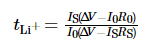
Among them, tLi+ is the transfer number of lithium ions, ΔV is the potential difference, R0 and RS are the interface impedance values of the electrode and electrolyte before and after the test, respectively, and I0 and IS are the initial state current and steady state current, respectively. The above tests were all carried out on the PARSTAT MC multi-channel electrochemical workstation of AMETEK, USA. The charge-discharge cycle performance of the battery was tested using the LAND CT3001A-1U battery test platform of Wuhan Landian Electronics Co., Ltd.
2 Results and discussion
2.1 Preparation and structural analysis of GCE
In this study, PEGDA was used as monomer, AIBN was used as polymerization initiator, and EC and DEC were introduced as plasticizers. A gel-state electrolyte with a cross-linked polymeric polyethylene glycol dimethacrylate (p(PEGDA)) was synthesized at 70 ℃. The polymerization reaction formula is shown in Figure 1(a). After adding the thermal initiator AIBN, PEGDA with two active terminal C=C groups rapidly undergoes intermolecular homopolymerization when heated to 70 °C. The active chains of AIBN make the molecular chains connect with each other or internally, and finally obtain the p(PEGDA) network skeleton structure, and successfully use the in-situ polymerization method to obtain the gel state electrolyte inside the battery. As shown in Figure S1, the three precursor solutions with different PEGDA contents all showed good wettability on the LiFePO4 positive electrode sheet, which is the key to obtain a good interfacial contact between the electrolyte and the electrode.

Fig. 1 Preparation and structural analysis of GCE
(a) Polymerization reaction of PEGDA; (b) Optical photographs of GCE-x; (c, d) FT-IR spectra of GCE-20, PEGDA and LE; (e) XRD patterns of GCE-x; Colorful figures are available on website
In order to obtain GCE with high ionic conductivity, LiTFSI, which has a high degree of dissociation in the polymer, was used as the lithium salt, and 0.2 mol/L LiDFOB was introduced to construct the gel network of the double-salt system. LiDFOB has good solubility and thermal stability, especially in film-forming properties. When carbonate solvents are in contact with lithium metal anodes, a large number of loose porous or dendritic lithium deposition layers are likely to be formed on the surface of lithium metal. The introduction of LiDFOB can assist in the formation of HF-free solid electrolyte interphase (Solid Electrolyte Interphase, SEI) layer and improve the compatibility with lithium metal anodes. At the same time, LiTFSI has a corrosive effect on metal current collectors, while LiDFOB can passivate aluminum metal and alleviate the corrosion effect of LiTFSI on current collectors. However, the single-salt electrolyte of LiDFOB exhibited higher impedance than the LiTFSI-LiDFOB dual-salt electrolyte of the same concentration. As shown in Figure S2, the Li||LiFePO4 battery was assembled using 1.2 mol/L LiDFOB and LiTFSI-LiDFOB gel electrolytes, respectively, and the impedance of the LiTFSI-LiDFOB battery was significantly smaller.
Existing research results show that LiTFSI and LiDFOB can have a synergistic effect, effectively improving the compatibility of the electrolyte with the lithium metal anode. Jiao Shuhong et al. used XPS and FT-IR to find that the double-salt electrolyte of LiTFSI and LiDFOB can passivate the aluminum current collector of the positive electrode and form a stable SEI layer on the surface of the lithium metal negative electrode to achieve long-term stable cycling of lithium metal batteries. On this basis, Liu Yue et al. [26] used hybrid molecular dynamics simulation to study the joint action mechanism of LiTFSI and LiDFOB in lithium metal batteries, and explained the protective effect of LiTFSI on LiDFOB. Studies have shown that the B-O bond of LiDFOB is relatively the weakest and prone to breakage. LiDFOB will rapidly decompose under the action of free radicals and react with lithium metal to produce free Li0 and boron atoms. The boron atom insertion reaction causes the solvent molecules in the electrolyte to decompose, and the resulting molecular fragments will continue to react with lithium salt molecular fragments and boron atoms. In the dilithium salt system, however, LiTFSI decomposes preferentially, relying on the "sacrifice mechanism" to protect LiDFOB, the decomposition rate of LiDFOB is significantly reduced. Thereby reducing the number of free Li0 and boron atoms, which can optimize the SEI layer and protect the lithium metal anode.
As shown in Figure 1(b), GCE-x is uniform and transparent jelly-like, no longer fluid. To further verify monomer polymerization, FT-IR was used to characterize the chemical structures of LE, PEGDA monomer and GCE-20. As shown in Fig. 1(c), all three samples show the typical absorption peak of C=O stretching vibration (~1726 cm-1). The absorption peak at 1280 cm-1 of GCE corresponds to the antisymmetric and symmetric stretching peaks of the ether bond, indicating that -(CH2CH2)n- in the monomer is not destroyed during the polymerization. The peaks at 1095 and 2867 cm−1 belong to -COOR and -CH2, respectively. As shown in Figure 1(d), the characteristic peak of the C=C bond of PEGDA is located at 1616-1636 cm-1, but it disappears in GCE, indicating that PEGDA has been polymerized completely.
Since lithium ions migrate only in the amorphous region of GCE, reducing the crystallinity of the electrolyte is beneficial to improve the ionic conductivity. Figure 1(e) is the XRD pattern of GCE-x. The three types of samples all have a unique diffraction absorption peak at 2θ=21°, indicating that the prepared electrolyte has an amorphous region accompanied by a small amount of crystallites. As the content of PEGDA increases, the peak area of the spectrum increases significantly, the proportion of the amorphous region of the gel electrolyte decreases, and the content of amorphous components in the electrolyte decreases, which is not conducive to ion migration.
2.2 Electrochemical performance of GCE and Li metal compatibility analysis
In order to study the compatibility of electrolytes with different polymer contents with lithium metal anodes in batteries, the impedance spectra of Li||Li symmetric batteries with GCE-x electrolytes in the initial state were analyzed (as shown in Figure S3). In the figure, the interface impedance values of the GCE-10 and GCE-20 batteries are both small, 93 and 152 Ω, respectively, and the GCE-30 battery reaches 409 Ω. It shows that the migration of lithium ions in GCE with higher polymer content needs to overcome a larger migration barrier, which is not conducive to the rapid conduction of lithium ions at the interface.
Observing the overpotential of the Li||Li symmetric battery in the charge-discharge cycle test, we can know the potential difference generated by the ion pair migration during this process, and then evaluate the lithium deposition/stripping behavior. Figure S4 shows the voltage-time curves of the Li||Li symmetric cell of GCE-x. The test temperature was 25 ℃, and the battery was charged and discharged under a constant current with a specific capacity of 0.5 mAh cm-2 and a current density of 0.5 mA cm-2. The initial overpotential of Li|GCE-10|Li cells was 22 mV, and the voltage increased to 137 mV after 250 h. The overpotential of the GCE-30 symmetric battery was 104 mV in the initial stage, and the overpotential rose rapidly in the subsequent cycles, reaching a peak value of 509 mV in 227 h and then dropped sharply, indicating that the battery had an internal short circuit. In contrast, the GCE-20 battery can operate at a low overpotential near 30 mV, and has the most stable electrochemical performance. The following will focus on the GCE-20 electrolyte.
The ionic conductivity of an electrolyte directly reflects the ability of ions to migrate in an electric field. The ionic conductivity of LE and GCE-20 was tested at 60, 50, 40, 30, 20, 10 and 0 ℃, respectively. As shown in Figure 2(a), the ionic conductivity of GCE-20 at 30 °C is 1.00 mS cm-1, and when the test temperature rises to 60 °C, the conductivity reaches 1.39 mS cm-1. This is because the activation energy decreases with the increase of test temperature, and the movement activity of polymer chain segments and lithium ions increases. However, the movement speed of polymer chain segments is obviously affected by temperature, so the conductivity of GCE-20 gel electrolyte changes more than that of electrolyte solution.

Fig. 2 Electrochemical performance of GCE-20
(a) Ionic conductivities of LE and GCE-20; (b) LSV curves of LE and GCE-20; (c) Current-time profile of Li|GCE-20|Li cell with inset showing corresponding Nyquist plots; (d) Voltage-time curves of symmetric Li||Li cells assembled with LE and GCE-20; (e) Nyquist plots of Li|GCE-20|Li cell after cycling; (f) Voltage-time and current density-time curves of Li|GCE-20|Li cell; Colorful figures are available on website
Improving the energy density of batteries requires ensuring the stability of the electrolyte at high operating voltages. Studies have shown that carbonyl-coordinated polymer-based electrolytes usually have a wide electrochemical window and good stability at high operating voltages. Figure 2(b) shows that the LSV curve of the GCE-20 battery begins to fluctuate significantly at 5.26 V, and it can be considered that the electrochemical window of the GCE-20 gel electrolyte reaches 5.26 V. In contrast, the electrochemical window of the commercial electrolyte is only 3.92 V. Therefore, the gel-state electrolyte has excellent electrochemical stability at high voltage.
In addition, the lithium ion migration number of the electrolyte is also one of the indicators to measure the lithium ion conductivity. It is defined as the ratio of the number of lithium ions passing through a section of the electrolyte perpendicular to the direction of lithium ion migration per unit time to the sum of anions and cations passing through the section. The higher the value, the larger the proportion of lithium ions in the ion migration process, and the higher the migration efficiency. Figure 2(c) is the chronoamperometry curve of the Li|GCE-20|Li battery, where the inset is the comparison of the electrochemical impedance of the battery before and after the test. According to formula (1), the lithium ion migration number of GCE-20 is 0.21. The introduction of additives or doping with inorganic fillers can obtain a higher lithium ion migration rate, which is not only beneficial to improve the charge and discharge rate of the battery, but also enhance its cycle stability.
During the charging and discharging process of Li||Li symmetric battery, the anions and cations in the electrolyte undergo counter-migration. When charging, lithium ions migrate to the negative electrode, and anions migrate to the positive electrode, and the opposite is true when discharging. Therefore, during the charging and discharging process, the ion concentration gradient between the positive and negative electrodes and the built-in electric field gradually increase, hindering the opposite movement of anions and cations, resulting in concentration polarization inside the battery, resulting in a change in overpotential. As shown in Figure 2(d), the Li|GCE-20|Li battery has an overpotential of 46 mV after stable cycling for 300 h. However, the overpotential generated by the Li|LE|Li battery during the test is significantly higher than that of the Li|GCE-20|Li battery (65~118 mV). This is because the growing lithium dendrites cause soft short circuits at some internal sites. The results show that the electrochemical behavior inside the GCE-20 battery is more ideal. Figure 2(e) is the EIS test of the symmetrical battery after 10, 20, 50 and 100 cycles. As the number of charge-discharge cycles increases, the battery impedance tends to decrease. During this process, a stable SEI layer was built between the electrolyte and lithium metal interface, and the interface contact was optimized, so that the interface impedance decreased significantly.
At 25 ℃, the Li|GCE-20|Li battery was subjected to 10 charge-discharge cycles at current densities of 0.2, 0.5, 1, 2, 0.2 and 0.5 mA cm-2, respectively. Figure 2(f) reflects the trend of the overpotential of the symmetric cell over time during this process. The overpotential at low current density is small and can remain relatively stable. After the current density increases, the overpotential increases accordingly, and there is no sudden increase/decrease in voltage during the process.
The morphology of the lithium sheet coating after cycling can visually characterize the deposition/stripping behavior of lithium inside the battery. The Li||Li symmetric battery was disassembled after charging and discharging for 100 h at a capacity of 0.5 mAh cm-2 and a current density of 0.5 mA cm-2, and the microscopic morphology of the cross-section and surface of the lithium metal sheet was observed by FESEM. As shown in Figure 3(a, b), the thickness of the untreated pristine lithium sheet is 353 µm, and the surface is flat and smooth. The interaction between the liquid electrolyte and lithium metal leads to the deposition of a large number of loose and porous lithium deposition layers on the surface of the lithium sheet of the Li|LE|Li battery, mostly in the shape of fine and uneven moss. When the thickness of the lithium metal sheet increases to 446 µm, there is an obvious volume expansion effect, and a large number of dendrites are generated. In contrast, the thickness of the lithium sheet in the Li|GCE-20|Li battery is 391 μm, and the surface deposition layer is dense and uniform, and there is no finely divided lithium coating (Fig. 3(c)). It shows that the gel-state electrolyte can effectively suppress the volume expansion of lithium metal anode. LiDFOB in GCE-20 can assist in the formation of a stable SEI layer to balance the internal potential of the battery, and delay the growth of lithium dendrites by inducing uniform deposition of lithium. Therefore, to a certain extent, it can optimize the lithium deposition/stripping behavior and protect the lithium metal anode.

Fig. 3 SEM images of metallic Li
Cross-sectional (up) and top-view (down) SEM images of (a) fresh metallic Li and lithium deposition morphology in symmetric Li||Li cells with (b) LE and (c) GCE-20
Subsequently, XPS surface element analysis was used to explore the composition of the SEI layer on the surface of the lithium metal anode under the action of the LiTFSI-LiDFOB double-salt system GCE. Figure S5 is the XPS spectrum of the lithium metal anode surface using LE and GCE-20. The spectrum of C1s (Fig. S5(a, d)) mainly has 4 signal peaks, corresponding to C-C/C-H at 284.8 eV. The two peaks at 286.4 and 289.4 eV correspond to C-O and C=O, respectively, and they are mainly derived from the decomposition products of carbonate solvents (such as ROCO2-, ROC-, etc.). The peak at 292.7 eV corresponds to CF3, which is mainly derived from the decomposition products of lithium salts. In the O1s spectrum (Figure S5(b, e)), the peaks at 531.1 and 532.3 eV correspond to C=O and C-O, respectively, and the relative content of C-O is significantly reduced, which is mainly related to the decrease in the content of decomposition products. Under the joint action of LiTFSI and LiDFOB, the formation of LiOCH3, Li2O2C2H4 and other by-products is restricted. In addition, unlike LE (Fig. S5(e)), in the F1s spectrum of GCE-20 (Fig. S5(f)), the signal peak of LiF is at 684.5 eV, and LiF can assist in the formation of a dense and stable SEI layer.
2.3 Electrochemical performance analysis of Li||LiFePO4 battery
LiFePO4 has the advantages of high capacity, long cycle life, and outstanding safety, and is a mainstream positive electrode active material. Its theoretical specific capacity is 170 mAh·g-1. At 25 ℃, the Li|GCE-20|LiFePO4 battery was charged and discharged 200 times at a constant current of 0.2C (1C=0.67 mA·cm-2). As shown in Figure 4(a, b), the discharge specific capacity of the first cycle is 141.4 mAh·g-1. The discharge specific capacity of the 200th lap is 131.4 mAh·g-1, the capacity retention rate reaches 92.95%, and the single-turn capacity decay is less than 0.04%. The platform voltage is stable, in line with the characteristics of LiFePO4 batteries. Coulombic efficiency, as an important indicator for evaluating battery cycle stability, refers to the ratio of battery discharge capacity to charge capacity during the same cycle. The first cycle coulombic efficiency of the Li|GCE-20|LiFePO4 battery is 97.8%. Due to the formation of the SEI layer during the first cycle discharge process, part of the irreversible capacity is generated, resulting in a low first cycle coulombic efficiency.

Fig. 4 Electrochemical performance of the Li|GCE-20|LiFePO4 cells
(a) Cycling performance and (b) corresponding voltage-capacity curves at 0.2C; (c) Rate performance and (d) corresponding voltage-capacity curves; Colorful figures are available on website
In addition, charge and discharge tests were performed on Li|GCE-20|LiFePO4 at 0.3C, 0.5C, 1C, 1.5C, and 0.5C rate currents to explore its rate performance. As shown in Fig. 4(c), when the current rate is 0.5C, the first cycle discharge specific capacity of the battery is 160.2 mAh·g-1. As the current rate increases, the discharge specific capacity of the battery decreases within a controllable range. The rate is increased to 2C, and the specific capacity of the first cycle discharge is 130 mAh·g-1. Subsequently, the current rate returned to 0.5C again, and the specific capacity of the first cycle discharge was 156.1 mAh·g-1. The relevant voltage-capacity curves are shown in Figure 4(d). The plateau voltage at different rates is stable without causing an increase in overpotential, and the battery shows good rate performance and reversibility.
3 Conclusion
PEGDA-based GCE was developed by thermally initiating in-situ polymerization. The FT-IR and XRD characterization analysis of GCE, combined with electrochemical tests, screened out the optimal GCE formulation. Further assemble the battery to study the electrochemical performance of the electrolyte, and analyze the protective effect of the electrolyte on the lithium metal negative electrode by observing the microscopic morphology and surface element characterization of lithium metal, explaining:
1) The GCE-x (x=10, 20, 30) prepared by in-situ polymerization can wet the electrode sheet well, and the electrolyte has the best electrochemical stability when the mass fraction of PEGDA is 20%.
2) The dilithium salt system of LiTFSI and LiDFOB is introduced, which can form a good interaction with the polymer components. The electrolyte has a wide electrochemical window (5.26 V) and high ionic conductivity (30 ℃, 1×10⁻³ S·cm-1). At the same time, the dilithium salt system can be used to construct a stable SEI layer and effectively protect the lithium metal anode.
3) Using GCE-20 to match the commercial LiFePO4 cathode material, the assembled full battery can stably charge and discharge for 200 cycles at a current of 0.2C, with a capacity retention rate of 92.95%, and exhibits good rate performance.
In summary, this work obtained a safe and excellent electrochemical performance of GCE, which provides an effective solution for the development of safe and stable high energy density lithium metal batteries.
Additional material:
S1 battery preparation process
Mix and grind LiFePO4, Ketjen Black and PVDF according to the target ratio, add the solvent N-Methylpyrrolidone (N-Methylpyrrolidone, NMP), fully stir and disperse, and obtain a uniform and viscous active material slurry. The slurry was scraped-coated on the aluminum foil with a flat coater, then transferred to a vacuum oven, and dried at 80 °C for 12 h. After cutting the electrode sheet, dry it again and transfer it to an anhydrous and oxygen-free glove box.
A gasket, shrapnel, and lithium metal sheet were placed in the center of the negative electrode case in sequence, and the thickness of the lithium metal sheet was 0.35 mm. Subsequently, the precursor solution of GCE was added dropwise on the center of the surface of the negative electrode (50 µL) using a pipette gun, and then the Celgard 2500 battery separator and the positive electrode sheet (Celgard 2500 battery separator) were placed in sequence. Before assembling the Li||LiFePO4 battery, the positive pole piece was weighed and the active material loading was recorded. The active material surface loading of the LiFePO4 positive electrode was 3.94 mg cm-2. Finally, pressurize and seal the battery on a battery sealing machine, transfer it to a 70 °C environment and heat it for 2 h to initiate polymerization to obtain a gel state electrolyte. In order to ensure that the electrolyte fully infiltrates the LiFePO4 pole piece, the battery needs to be left to stand for 1 h after assembly.

Fig. S1 Contact angles between polymer precursor solution and cathodes
(a) LE; (b) GCE-10; (c) GCE-20; (d) GCE-30

Fig. S2 Nyquist plots of GCE assembled Li||LiFePO4 cells with different lithium salt

Fig. S3 Nyquist plots of symmetric Li||Li cells assembled with GCE-x electrolytes

Fig. S4 Voltage-time profiles of symmetric Li||Li cells assembled with GCE-x electrolytes

Fig. S5 XPS spectra of metallic Li anode in symmetric Li||Li cells
(a, d) C1s, (b, e) O1s, (c, f) F1s XPS spectra of metallic Li anode with (a-c) LE and (d-f) GCE-20
[1] GOODENOUGH J B, KIM Y.
Challenges for rechargeable Li batteries
Chemistry of Materials, 2010, 22(3):587.
[2] ZHAO J, LIAO L, SHI F, et al.
Surface fluorination of reactive battery anode materials for enhanced stability
Journal of the American Chemical Society, 2017, 139(33):11550.
[3] TARASCON J M, ARMAND M.
Issues and challenges facing rechargeable lithium batteries
Nature, 2001, 414(6861):359.
[4] ZHI J, YAZDI A Z, VALAPPIL G, et al.
Artificial solid electrolyte interphase for aqueous lithium energy storage systems
Science Advances, 2017, 3(9):e1701010.
[5] JUN K, SUN Y, XIAO Y, et al.
Lithium superionic conductors with corner-sharing frameworks
Nature Materials, 2022, 21: 924.
[6] LIU J, BAO Z, CUI Y, et al.
Pathways for practical high-energy long-cycling lithium metal batteries
Nature Energy, 2019, 4(3):180.
[7] DUNN B, KAMATH H, TARASCON J M.
Electrical energy storage for the grid: a battery of choices
Science, 2011, 334(6058):928.
[8] MAUGER A, JULIEN C M, PAOLELLA A, et al.
Building better batteries in the solid state: a review
Materials, 2019, 12(23):3892.
[9] MANTHIRAM A, YU X, WANG S.
Lithium battery chemistries enabled by solid-state electrolytes
Nature Reviews Materials, 2017, 2(4):16103.
[10] ZHOU D, SHANMUKARAJ D, TKACHEVA A, et al.
Polymer electrolytes for lithium-based batteries: advances and prospects
Chem, 2019, 5(9):2326.
[11] TAN S J, YUE J, TIAN Y F, et al.
In-situ encapsulating flame- retardant phosphate into robust polymer matrix for safe and stable quasi-solid-state lithium metal batteries
Energy Storage Materials, 2021, 39: 186.
[12] ZHAO Q, LIU X, STALIN S, et al.
Solid-state polymer electrolytes with in-built fast interfacial transport for secondary lithium batteries
Nature Energy, 2019, 4(5):365.
[13] ZHOU Z, FENG Y, WANG J, et al.
A robust, highly stretchable ion-conducive skin for stable lithium metal batteries
Chemical Engineering Journal, 2020, 396: 125254.
[14] WILKEN S, TRESKOW M, SCHEERS J, et al.
Initial stages of thermal decomposition of LiPF6-based lithium ion battery electrolytes by detailed Raman and NMR spectroscopy
RSC Advances, 2013, 3(37):16359.
[15] LIU F Q, WANG W P, YIN Y X, et al.
Upgrading traditional liquid electrolyte via in situ gelation for future lithium metal batteries
Science Advances, 2018, 4(10):eaat5383.
[16] XU C, SUN B, GUSTAFSSON T, et al.
Interface layer formation in solid polymer electrolyte lithium batteries: an XPS study
Journal of Materials Chemistry A, 2014, 2(20):7256.
[17] WEI Z, CHEN S, WANG J, et al.
Superior lithium ion conduction of polymer electrolyte with comb-like structure via solvent-free copolymerization for bipolar all-solid-state lithium battery
Journal of Materials Chemistry A, 2018, 6(27):13438.
[18] DI NOTO V, LAVINA S, GIFFIN G A, et al.
Polymer electrolytes: present, past and future
Electrochimica Acta, 2011, 57(15):4.
[19] XUE Z, HE D, XIE X.
Poly(ethylene oxide)-based electrolytes for lithium-ion batteries
Journal of Materials Chemistry A, 2015, 3(38):19218.
[20] MINDEMARK J, LACEY M J, BOWDEN T, et al.
Beyond PEO-Alternative host materials for Li+-conducting solid polymer electrolytes
Progress in Polymer Science, 2018, 81: 114.
[21] ARAVINDAN V, GNANARAJ J, MADHAVI S, et al.
Lithium-ion conducting electrolyte salts for lithium batteries
Chemistry-A European Journal, 2011, 17(51):14326.
[22] XU K.
Electrolytes and interphases in Li-ion batteries and beyond
Chemical Reviews, 2014, 114(23):11503.
[23] YANG H, ZHUANG G V, ROSS JR P N.
Thermal stability of LiPF6 salt and Li-ion battery electrolytes containing LiPF6
Journal of Power Sources, 2006, 161(1):573.
[24] LI Q, LIU G, CHENG H, et al.
Low-temperature electrolyte design for lithium-ion batteries: prospect and challenges
Chemistry-A European Journal, 2021, 27(64):15842.
[25] JIAO S, REN X, CAO R, et al.
Stable cycling of high-voltage lithium metal batteries in ether electrolytes
Nature Energy, 2018, 3(9):739.
[26] LIU Y, YU P, SUN Q, et al.
Predicted operando polymerization at lithium anode via boron insertion
ACS Energy Letters, 2021, 6(6):2320.
[27] CAO W, LU J, ZHOU K, et al.
Organic-inorganic composite SEI for a stable Li metal anode by in-situ polymerization
Nano Energy, 2022, 95: 106983.
[28] CHENG S, SMITH D M, LI C Y.
How does nanoscale crystalline structure affect ion transport in solid polymer electrolytes?
Macromolecules, 2014, 47(12):3978.
[29] JOHANSSON P.
First principles modelling of amorphous polymer electrolytes: Li+-PEO, Li+-PEI, and Li+-PES complexes
Polymer, 2001, 42(9):4367.
[30] SUN B, MINDEMARK J, EDSTRÖM K, et al.
Polycarbonate- based solid polymer electrolytes for Li-ion batteries
Solid State Ionics, 2014, 262: 738.
[31] SILVA M M, BARROS S C, SMITH M J, et al.
Characterization of solid polymer electrolytes based on poly (trimethylenecarbonate) and lithium tetrafluoroborate
Electrochimica Acta, 2004, 49(12): 1887.
[32] BARBOSA P, RODRIGUES L, SILVA M M, et al.
Characterization of pTMCnLiPF6 solid polymer electrolytes
Solid State Ionics, 2011, 193(1):39.