Chinese
 français
 Deutsch
 italiano
 español
 português
 Nederlands
 日本語
日本語 한국의
한국의




- Home
- >
- Electrode Preparation
- >
- Battery Coating Machine
- >
- Doctor Blade Coating Machine for Battery Electrode
Categories
Hot Products
Loading...

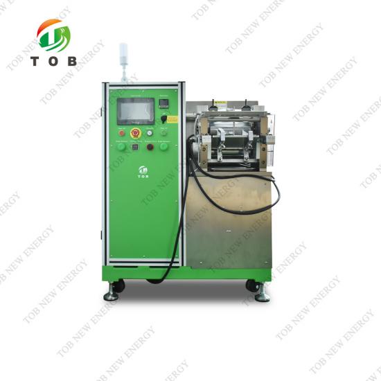
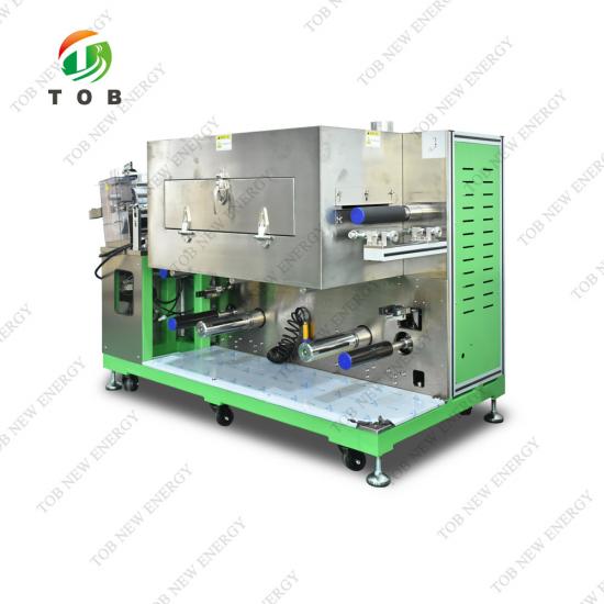
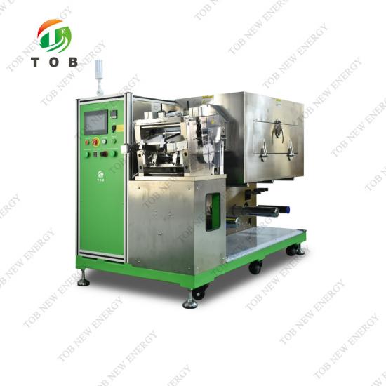
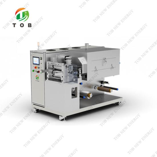
Doctor Blade Coating Machine for Battery Electrode
Brand:
TOB NEW ENERGYitem no.:
TOB-KD200order(moq):
1setPayment:
L/C,T/Tproduct origin:
Chinashipping port:
XIAMEN
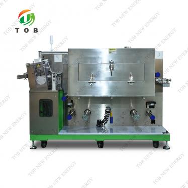
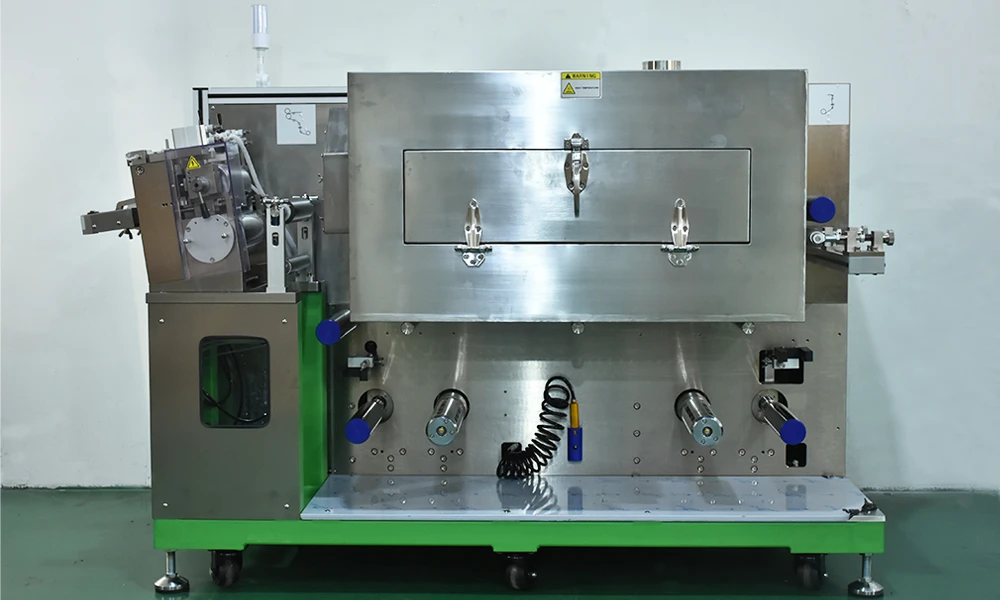
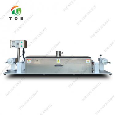
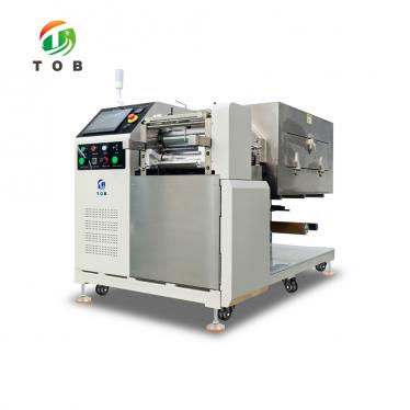
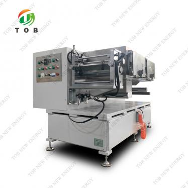
TOB-KD200 Precision Doctor Blade Coating Machine with Integrated Drying for Battery Electrode R&D and Pilot Production
Product Overview and Ideal Applications
A continuous doctor blade coating machine deposits a precisely metered liquid film onto a moving web substrate using a rigid knife edge (the "doctor blade" or “comma bar”) positioned at a controlled gap above the substrate. The TOB‑KD200 is a benchtop‑scale continuous coater specifically engineered for lithium‑ion and sodium‑ion battery electrode R&D and small‑scale pilot production. It accepts a wide range of cathode and anode slurries—NMC, LFP, LCO, LMO, graphite, silicon‑carbon composites—and coats them onto aluminium or copper foil (8–30 µm Al, 6–30 µm Cu) with a dry thickness repeatability of ±3 µm across a maximum coating width of 200 mm.
Unlike manual doctor‑blade rigs that produce one sheet at a time and rely heavily on operator skill, the TOB‑KD200 operates as a continuous roll‑to‑roll line. An automatic unwind system with tension control and web‑edge guiding feeds the foil onto a precision‑ground steel coating roller (Ø100 mm, hard‑chrome‑plated, TIR ≤ ±1.5 µm). A dual‑sided comma‑blade assembly, positioned before the drying oven, meters the slurry with micrometer‑level repeatability. The coated web then passes into a two‑section, independently heated hot‑air drying tunnel (each 1 m long) that simultaneously blows temperature‑controlled air onto both the top and bottom of the foil, achieving rapid, uniform drying without curling. The dried electrode is re‑wound on a second pneumatic shaft at the exit, complete with web‑edge correction.
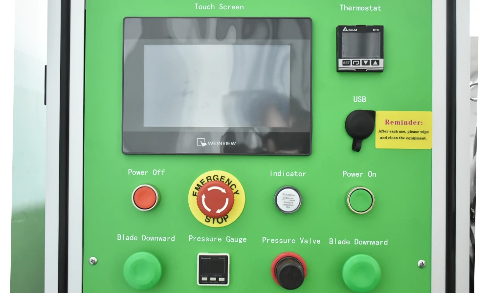
All process parameters—coating speed (0–0.5 m/min), oven temperature (up to 150 °C per section), and tension—are controlled via a PLC with a touch‑screen interface. The oven employs analogue‑signal‑controlled solid‑state relays for heating, giving precise ±0.5 °C temperature regulation and long heater life. An optional solvent‑recovery system can be integrated for NMP‑based slurries.
Ideal for:
- Battery R&D laboratories that need to produce hundreds of metres of consistent, high‑quality electrode strip for coin‑cell or single‑layer pouch‑cell testing.
- Pilot‑line process engineers optimising slurry formulations, coating gaps, and drying profiles before transferring to full‑scale production coaters.
- Universities and research institutes investigating novel electrode materials (solid‑state, sodium‑ion, lithium‑sulfur) where uniform electrode fabrication is critical to obtaining meaningful electrochemical data.
- Any group that has outgrown manual sheet coating and requires the repeatability and throughput of a continuous roll‑to‑roll machine in a compact, benchtop‑friendly format.
Where This Coater Fits in Battery Electrode Manufacturing
In the lithium‑ion cell production chain, the TOB‑KD200 operates at the electrode preparation stage, immediately after slurry mixing and before calendaring. The process flow is:
- Slurry preparation – Active material, carbon black, and binder are mixed in a planetary mixer.
- Coating (the TOB‑KD200’s role) – The slurry is pumped or poured onto the moving aluminium or copper foil. The comma bar (doctor blade) meters the slurry to a precise wet film thickness. The coated foil then passes through the drying tunnel where the solvent (NMP or water) is evaporated.
- Calendaring – The dried electrode is compressed to the target density.
- Slitting / cutting – The coated foil is slit to the final electrode width, and individual electrode sheets are punched or cut.
The Coating step is arguably the most critical in determining the electrode's final quality and the cell's performance. A poorly controlled coating process—streaks, thickness variations, pinholes, binder migration—cannot be corrected by subsequent steps. The TOB‑KD200 provides the precision and consistency that manual coating cannot achieve, ensuring that each electrode strip is a faithful representation of the slurry's intrinsic properties.
Key process considerations specific to this machine:
- Tension control: The TOB‑KD200 uses automatic constant‑tension control on both unwind and rewind. This is especially important for ultra‑thin foils (8 µm Al, 6 µm Cu) which can stretch or wrinkle if the tension is too high or too low. The maximum unwind roll diameter is 250 mm, with a weight capacity of 50 kg per reel.
- Web guiding: An automatic web‑edge guide at the unwind ensures that the foil tracks straight into the coating head. A second edge‑guide at the exit of the oven corrects any wander acquired during drying, so that the re‑wound roll is perfectly aligned.
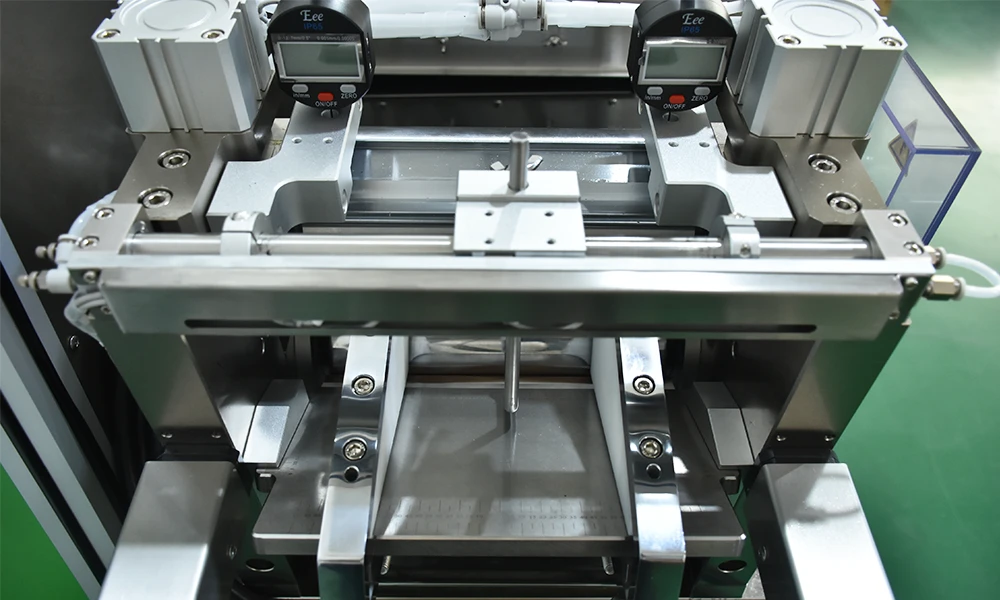
- Dual‑sided comma bar: The machine is equipped with a double‑sided doctor blade assembly. The blade can be positioned on either side of the foil, or both sides simultaneously if the application requires a primer coat on the reverse side. The gap is adjusted by precision lead screws.
- Solvent handling: The drying tunnel exhausts solvent‑laden air. For NMP (boiling point 204 °C), the optional solvent‑recovery system condenses the vapour for re‑use, reducing solvent cost and environmental emissions.
 |
 |
How the Doctor Blade Coating Machine Works
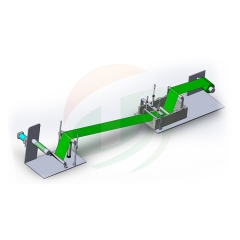
The TOB‑KD200 functions as a continuous, web‑fed precision coater. Here is how the entire system operates, from reel to reel:
- Unwind and tensioning: A roll of bare aluminium or copper foil is loaded onto a 3‑inch pneumatic expanding shaft at the unwind station. The foil is threaded over a series of aluminium guide rollers (surface‑oxidised for wear resistance and chemical inertness) and through the web‑edge guide. The tension is set to the desired value via the PLC, which controls a motorised brake or torque motor on the unwind shaft. Constant tension is maintained even as the roll diameter decreases.
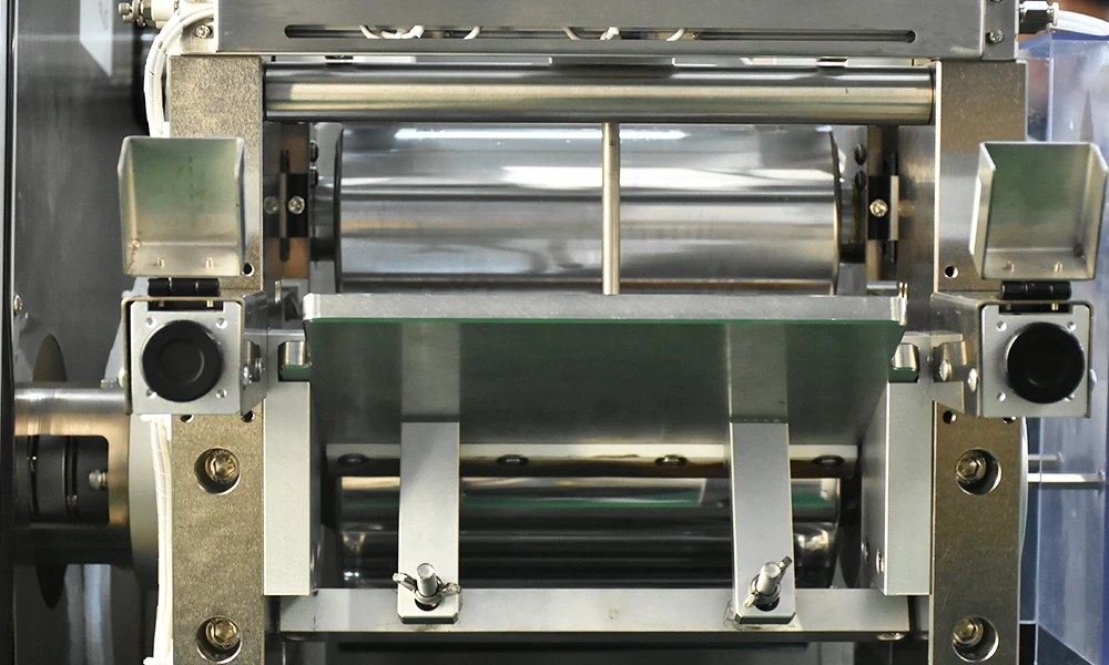
- Coating application: The foil passes over the precision coating roller (Ø100 mm steel roller, hard‑chrome‑plated, with a roundness and straightness of ≤ ±1.5 µm and a surface finish of Ra 0.4). Slurry is manually or pump‑fed into the gap between the foil and the comma bar. The comma bar (also Ø100 mm with identical precision) is positioned above the foil, and its gap—the wet film thickness—is adjusted by precision lead‑screw mechanisms on both ends. The coating width is up to 200 mm (the effective coating width is 200 mm on a 230 mm roller face). The doctor blade is equipped with micrometer‑scale adjustment, achieving a dry‑thickness repeatability of ±3 µm for a single‑sided dry film of 20–200 µm.
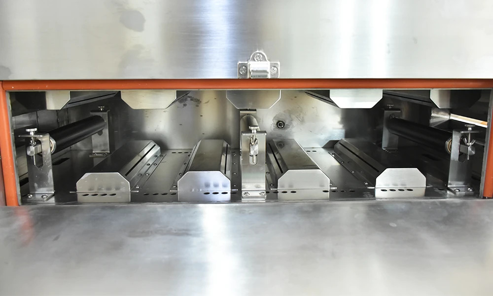
- Drying: The wet‑coated web immediately enters the hot‑air drying tunnel. The tunnel consists of two independently heated sections, each 1 metre long, arranged one after the other. Each section has its own heater (3 kW, analogue‑signal‑controlled solid‑state relays), its own temperature sensor, and its own over‑temperature safety cut‑off. The hot air is blown through specially designed slot nozzles from both the top and bottom toward the foil, ensuring uniform drying on both sides and minimising the tendency to curl. The internal temperature can be set up to 150 °C, with a temperature uniformity of ≤±2.5 °C within a single section. The fan is a centrifugal type, constructed from SUS 304 stainless steel for corrosion resistance. Because the drying air is fully contained and exhausted, the solvent vapour is directed to a vent or to the optional solvent‑recovery system.
- Rewind and edge correction: After drying, the finished electrode web passes through a second web‑edge guide that corrects any lateral drift accumulated during drying. The foil is then wound onto a second 3‑inch pneumatic expanding shaft at the rewind station, which is also under automatic constant‑tension control. The entire machine, mounted on a welded steel frame with lockable castors, occupies a footprint of L1700 × W900 × H1100 mm and weighs 570 kg net (700 kg gross).
Control system:
A PLC coordinates the unwind tension, coating roller speed (0–0.5 m/min), oven temperature setpoints and safety interlocks, and rewind tension. The touch‑screen interface provides a dashboard for all parameters and stores recipes. The analogue‑signal heating control ensures smooth, contactor‑free power modulation, extending the life of the heaters and providing tight temperature stability of ±0.5 °C.
Key Engineering Advantages of the TOB‑KD200
- ±3 µm Dry‑Film Thickness Accuracy: The combination of a precision‑ground comma bar (TIR ≤ ±1.5 µm, Ra 0.4) and a rigidly supported coating roller of equal precision ensures that the metered wet film thickness is translated into a highly consistent dry film. This repeatability is essential for producing multiple electrodes with identical areal capacity—a fundamental requirement for valid comparative electrochemical testing.
- Dual‑Sided Hot‑Air Drying Prevents Curl and Delamination: Many lab‑scale coaters dry the electrode from one side only, which causes the solvent to evaporate preferentially from the top, leading to binder migration and severe curl. The TOB‑KD200’s tunnel blows heated air simultaneously onto the top and bottom of the coated foil, ensuring symmetric drying and a flat, handleable electrode. The two‑zone independent temperature control allows a gentle ramp (e.g., 80 °C in the first section, 120 °C in the second) to prevent skinning and cracking.
- Automatic Tension Control and Web‑Edge Guiding: The unwind and rewind stations are under closed‑loop tension control, adjustable via the PLC. This prevents elongation of thin copper foil (as thin as 6 µm) during coating and start‑up transients. The web‑edge guide at the unwind maintains the foil centred on the coating roller, and the exit guide corrects any wander, so the re‑wound roll is neatly wound without telescoping.
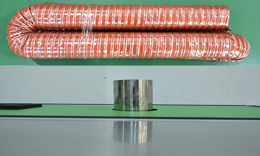
- Corrosion‑Resistant Design for NMP and Aqueous Slurries: The guide rollers are surface‑oxidised aluminium, the coating roller is hard‑chrome‑plated steel, and the drying‑tunnel fans and ducting are SUS 304 stainless steel. This selection of materials resists corrosion from NMP, water, and the mild acids/bases that can be present in aqueous slurries, giving the machine a long service life.
- Compact Footprint with Production‑Grade Capabilities: At L1700 × W900 × H1100 mm and 570 kg, the TOB‑KD200 fits in a standard laboratory bay. Yet it incorporates all the elements of a production coater—unwind/rewind tension control, web guiding, precision metering, multi‑zone drying—allowing direct transfer of process parameters from the laboratory to the pilot line.
- Flexible Slurry Compatibility (Viscosity 2000–12,000 mPa·s, Solid Content 20–85 %): The doctor blade method is inherently tolerant of a wide range of slurry rheologies, from low‑viscosity water‑based anode formulations to thick, paste‑like NMP cathode mixtures. The machine’s parameters can be adjusted to accommodate these variations: higher coating speeds for thin, low‑viscosity slurries; slower speeds and a wider gap for high‑viscosity, high‑solid‑content pastes.
- Optional Solvent‑Recovery System: For laboratories and pilot lines that use expensive or regulated solvents (such as NMP), an optional solvent‑recovery unit can be connected to the dryer exhaust. This condenses and collects the solvent for re‑use, reducing operating costs and environmental impact.
Complete Technical Specifications
Equipment Capabilities
|
No. |
Item |
Technical Parameter |
Remarks |
|
1 |
Suitable chemistries |
NMC, LFP, LCO, LMO, graphite, silicon‑carbon, and other battery cathode and anode coating processes |
|
|
2 |
Coating method |
Doctor blade continuous coating |
|
|
3 |
Coating speed |
0–0.5 m/min |
Depending on drying condition |
|
4 |
Substrate thickness |
Aluminium foil (Al): 8–30 µm, Copper foil (Cu): 6–30 µm |
|
|
5 |
Roller face width |
230 mm |
|
|
6 |
Guaranteed coating width |
Within 200 mm |
|
|
7 |
Doctor roller |
Ø100 mm |
|
|
8 |
Coating accuracy |
±3 µm |
|
|
9 |
Suitable slurry viscosity |
2000–12,000 mPa·s |
|
|
10 |
Single‑side dry thickness range |
20–200 µm |
|
|
11 |
Solvent type |
Oily solvent NMP (s.g.=1.033, b.p.=204 °C); aqueous solvent H₂O/NMP (s.g.=1.000, b.p.=100 °C) |
|
|
12 |
Suitable solid content range |
20–85 % |
|
|
13 |
Coating dimensional accuracy (mm) |
L ≤ ±1, W ≤ ±0.5 |
L: length direction, W: width direction |
|
14 |
Front‑back alignment accuracy (mm) |
L ≤ ±1, W ≤ ±0.5 |
Unwind and Coating Head Section
|
No. |
Item |
Technical Parameter |
Remarks |
|
1 |
Guide roller mounting structure |
Rigid steel frame mounting |
|
|
2 |
Guide roller surface treatment |
Aluminium roller, surface oxidised |
|
|
3 |
Tension control system |
Automatic constant‑tension control |
|
|
4 |
Roll loading method |
Material roll secured by 3‑inch pneumatic expanding shaft; unwind uses single pneumatic shaft |
|
|
5 |
Maximum unwind roll diameter |
Ø250 mm |
|
|
6 |
Maximum load per pneumatic shaft |
50 kg |
|
|
7 |
Number of unwind pneumatic shafts |
1 |
|
|
10 |
Guide roller surface treatment |
Aluminium roller, surface oxidised |
|
|
11 |
Doctor blade structure |
Double‑sided comma bar |
|
|
12 |
Coating roller (steel roller) |
Surface hard‑chrome‑plated |
|
|
14 |
Doctor blade gap height adjustment |
Precision lead‑screw adjustment |
|
|
15 |
Single machine head position |
Installed before the drying tunnel, operator side |
Drying Tunnel (Oven)
|
No. |
Item |
Technical Parameter |
Remarks |
|
1 |
Oven structure |
Two‑layer, independently heated, top‑and‑bottom arrangement |
|
|
2 |
Oven length |
1 m per section |
|
|
3 |
Material |
SUS 304 stainless steel |
|
|
4 |
Temperature control |
Divided into normal operating temperature control, over‑temperature monitoring alarm protection control, and heating main power cut‑off; each section is fully independently controlled |
|
|
5 |
Heating method |
Analogue signal power control, hot‑air circulation structure, accuracy ±0.5 °C |
|
|
6 |
Single‑section oven heating power |
3 kW |
|
|
7 |
Maximum oven temperature |
Designed Max 150 °C, temperature difference within a single section ≤ ±2.5 °C |
|
|
8 |
Air blowing method |
Top‑and‑bottom blowing, top and bottom air plenums share the heater |
|
|
9 |
Nozzle structure |
Nozzle slots formed by a dedicated die |
|
|
10 |
Fan control |
Contactor control |
|
|
11 |
Heating control |
Analogue signal power control, solid‑state relay |
|
|
12 |
Fan material |
SUS 304 stainless steel |
|
|
13 |
Solvent recovery system |
Optional |
Rewind Section
|
No. |
Item |
Technical Parameter |
Remarks |
|
1 |
Automatic web‑edge guide |
Installed at the exit of the drying tunnel |
|
|
2 |
Automatic tension control |
Automatic constant‑tension control |
|
|
3 |
Mounting structure |
Rigid steel frame mounting |
|
|
4 |
Number of rewind pneumatic shafts |
1 |
Single‑arm rewind |
Machine Dimensions and Weight
|
Parameter |
Value |
|
Dimensions (L × W × H) |
L1700 × W900 × H1100 mm |
|
Net weight |
570 kg |
|
Gross weight |
700 kg |
|
Castors |
Installed |
Hardware Precision
|
No. |
Item |
Technical Parameter |
Remarks |
|
1 |
Doctor blade (comma bar) |
Roundness (TIR) ≤ ±1.5 µm, Ra 0.4, straightness ≤ ±1.5 µm |
|
|
2 |
Coating roller (steel roller) |
Roundness (TIR) ≤ ±1.5 µm, Ra 0.4, straightness ≤ ±1.5 µm |
Installation Environment Requirements
|
Item |
Requirement |
|
Ambient temperature (coating head area) |
25–30 °C |
|
Ambient temperature (other areas) |
10–40 °C |
|
Relative humidity (cathode side) |
≤ 35 % RH |
|
Relative humidity (anode side, other areas) |
≤ 98 % RH |
Utilities Requirements
|
Utility |
Specification |
|
Power supply |
3‑phase, 380 V, 50 Hz, voltage fluctuation range: +8 % to –8 %; starting total power 6 kW |
|
Compressed air |
Dried, filtered, and regulated; outlet pressure ≥ 5.0 kg/cm² |
 |
 |
Recommended Coating Parameters for Common Electrode Formulations (Starting Points)
These are pilot‑proven settings for the TOB‑KD200 with a typical 200 mm wide foil. All assume the slurry is well‑dispersed and degassed. Adjust drying profiles based on the actual residual moisture measured.
|
Electrode |
Substrate |
Slurry Viscosity (approx.) |
Coating Speed (m/min) |
Comma Bar Gap (µm) |
Drying Profile (Section 1 / Section 2) |
Target Dry Coating Thickness |
|
NMC622 cathode (PVDF/NMP) |
Al foil 15 µm |
4000–6000 mPa·s |
0.3 |
180 |
90 °C / 120 °C |
~80 µm |
|
LFP cathode (PVDF/NMP or aqueous) |
Al foil 15 µm |
5000–8000 mPa·s |
0.2 |
220 |
80 °C / 110 °C |
~100 µm |
|
Graphite anode (CMC/SBR, aqueous) |
Cu foil 10 µm |
3000–5000 mPa·s |
0.4 |
150 |
70 °C / 100 °C |
~70 µm |
|
Silicon‑graphite anode (PAA, aqueous) |
Cu foil 8 µm |
6000–10,000 mPa·s |
0.15 |
200 |
60 °C / 90 °C + extended dwell |
~90 µm |
|
LCO cathode (PVDF/NMP) |
Al foil 20 µm |
5000–7000 mPa·s |
0.3 |
200 |
100 °C / 130 °C |
~90 µm |
Note: The comma bar gap is set larger than the target wet thickness to account for the slurry’s rheology and the hydrodynamic metering effect. The actual relationship is empirically determined for each slurry type.
Why Choose TOB‑KD200 Over a Manual Doctor Blade or a Benchtop Sheet Coater
|
Feature |
TOB‑KD200 Continuous Coater |
Manual Doctor Blade (Sheet) |
Benchtop Slot‑Die Coater (Discrete Sheet) |
|
Coating format |
Continuous roll‑to‑roll |
Single sheet, lab‑scale |
Single sheet, often manual feed |
|
Throughput |
Up to 0.5 m/min continuously |
1 sheet every 3–5 minutes (manual labour) |
1 sheet per minute (automated) |
|
Drying method |
Integrated dual‑sided hot‑air, two zones |
External oven or air dry |
Heated bed or external oven |
|
Tension control |
Automatic, constant‑tension, both unwind and rewind |
Manual taping or none |
None, sheet is vacuum‑held during coating |
|
Web‑edge guide |
Auto‑corrects before coating and after drying |
Not applicable |
Not applicable |
|
Thickness accuracy |
±3 µm dry |
Typically ±10 µm or more, operator‑dependent |
±5 µm achievable with skilled operation |
|
Suitable for scaling |
Direct parameter transfer to pilot/production line |
No direct transfer |
Limited transfer, mainly for formulation R&D |
|
Material utilisation |
High, continuous web (minimal start‑up waste) |
Low, slurry leftover on blade/foil edges |
Medium, limited slurry in syringe/die |
|
Glovebox operation |
Not designed for glovebox (ambient operation) |
Can be placed inside glovebox |
Can be placed inside glovebox |
|
Cost |
Higher capital, justified by throughput and consistency |
Low capital, high labour |
Medium capital, lower labour |
Why research groups invest in the TOB‑KD200:
If you are making more than a few electrodes per week, a manual doctor blade becomes a bottleneck. Worse, the variability introduced by hand‑coating can mask the true electrochemical effect of your material innovation. The TOB‑KD200 takes the operator out of the equation for the critical coating step, allowing you to produce hundreds of identical electrodes in an afternoon, with every centimetre of the strip a faithful replica of the one before. And when you are ready to scale, the parameters you developed on this machine transfer directly to larger coaters, because the process is the same—only the width changes.
 |
 |
Engineering FAQ — Doctor Blade Coating for Battery Electrodes
Q1: How do I clean the comma bar and coating roller between different slurry batches?
After coating, wipe the comma bar and coating roller with a lint‑free cloth soaked in the slurry's solvent (NMP for cathode slurries, deionised water for aqueous anode slurries). Never use metal scrapers. Dry the surfaces with a clean cloth. For a complete changeover between chemistries (e.g., NMC to LFP), disassemble the doctor blade assembly and ultrasonically clean the components in solvent. Inspect the blade edge for nicks or deposits.
Q2: The quoted coating speed is 0–0.5 m/min, but can I run slower if my slurry dries slowly?
Yes. The speed is continuously adjustable down to near zero. The drying capability depends on the oven temperature, the air velocity (which is fixed by the fan, but the temperature can be adjusted), and the residence time (which is the length of the oven divided by the coating speed). With two 1 m oven sections, a coating speed of 0.1 m/min gives a total drying time of approximately 20 minutes (10 min per section). If your slurry still feels tacky, reduce the speed further or increase the oven temperature. The PLC allows you to fine‑tune the speed.
Q3: Can I coat both sides of the foil in a single pass?
The TOB‑KD200 is primarily set up for single‑side coating. To coat the second side, the first side must be dried, and the roll can be reloaded onto the unwind with the uncoated side facing the doctor blade. Some users rig a guide to flip the foil in the oven section, but this is not a standard feature. For double‑side simultaneous coating, a slot‑die or comma‑coater with a dedicated two‑side head is required—contact TOB for such systems.
Q4: What maintenance does the drying tunnel require?
The fans and ducting should be inspected every 6 months for solvent residue build‑up, especially if coating NMP slurries. NMP is a high‑boiling solvent and can condense in cool spots of the exhaust ducting. The optional solvent‑recovery system will reduce this accumulation. The heaters (3 kW per section) are robust but should be checked for correct current draw annually. All electrical connections must be inspected, and the solid‑state relays may need replacement after several years of cycling.
Q5: Is the machine suitable for coating solid‑state electrolyte slurries that may contain ceramic powders (LLZO, LATP) which are abrasive?
The hard‑chrome‑plated coating roller and the doctor blade are resistant to mild abrasion, but ceramic powders can accelerate wear over time. Monitor the roller surface for loss of the chrome layer (visible as a dull or coppery spot). If coating abrasives is a regular task, you may need to inspect the blade and roller more frequently and budget for re‑chroming every few years. The stainless‑steel oven interior is well‑suited to the task.
Ready to move beyond manual sheet coating to a continuous, production‑representative electrode fabrication process? Request a quotation for the TOB‑KD200. Include your target electrode width, slurry type, and desired throughput, and our process engineers will provide a detailed specification review and integration recommendations.
tob.amy@tobmachine.com | +86 181 2071 5609
You May Also Need
- TOB-SY300J Roll-to-Roll Coating Machine for Lithium Battery Electrode — A larger‑scale continuous coater designed for pilot and small‑batch production, offering higher throughput and wider coating widths than the benchtop TOB‑KD200.
- TOB-TBJ-180C Desktop Roll‑to‑Roll Continuous Coating Machine — A compact, bench‑friendly roll‑to‑roll coater ideal for laboratory‑scale electrode fabrication where space is limited but continuous coating is required.
- TOB-JS350-3.0 High Precision Slot Die Coating Machine for Lithium Battery Electrode — An alternative coating method using a slot‑die head for ultra‑uniform films with extremely tight thickness control, complementing the doctor blade technique.
- TOB-NMP-1 NMP Solvent Processing System — A dedicated solvent recovery and purification unit that captures evaporated NMP from the dryer exhaust of the TOB‑KD200, enabling safe reuse and reducing environmental emissions.
Previous:
Dual-Mode Battery Electrode Coating Machine (Slot Die & Transfer)Next:
Battery Electrode Transfer Coating Machine
If you are interested in our products and want to know more details,please leave a message here,we will reply you as soon as we can.

 subscribe to us