
- Home
- >
Coin Cell Equipment
- >
Lab Coater
- >
Lab Coater Desktop Slot Die Coating Machine
Categories
Hot Products

Loading...
Lab Coater Desktop Slot Die Coating Machine
Brand:
TOB NEW ENERGYitem no.:
TOB-JYCM-250order(moq):
1Payment:
L/C,T/Tproduct origin:
Chinashipping port:
XIAMEN
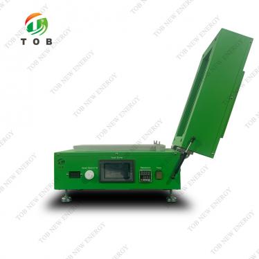
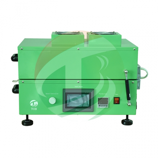
TOB-JYCM-250 Desktop Slot Die Coating Machine for Lithium-Ion Battery Electrode R&D
1. Product Overview and Ideal Applications
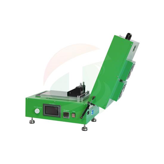
A slot die coating machine applies a precisely metered liquid film onto a moving substrate by extruding the fluid through a narrow, machined gap directly onto the surface. The TOB-JYCM-250 brings this proven industrial-scale coating principle to the laboratory benchtop in a compact, fully integrated system designed specifically for battery electrode research. Unlike manual doctor blade or wire‑wound rod coating—where film thickness depends heavily on operator skill—the TOB-JYCM-250 uses a syringe pump to feed slurry into a slot die head at a controlled rate while a motorised linear stage moves the substrate at a precisely set speed, yielding films with exceptional thickness uniformity and run‑to‑run repeatability.
The complete coating‑to‑drying workflow is contained in a single unit. An aluminium vacuum plate holds the current collector foil perfectly flat during coating. Immediately after coating, the die head is lifted away and a heated cover is placed over the wet film, enabling in‑situ drying at temperatures up to 130 °C with ±1 °C uniformity. This eliminates the need to transfer the delicate wet electrode to a separate oven, reducing the risk of damage or contamination. A PLC‑driven touch screen manages all motion parameters—coating speed, stroke length, syringe piston feed rate—and can store multiple recipes for different slurry types.
Ideal for:
- University and corporate R&D labs fabricating lithium‑ion battery electrodes (NMC, LFP, LCO, graphite, silicon composite) for coin‑cell or single‑layer pouch‑cell evaluation.
- Process development engineers systematically optimising slurry formulation and coating parameters before scaling to pilot roll‑to‑roll coaters.
- OLED, organic photovoltaic, and conductive polymer film research groups requiring smooth, pinhole‑free thin films on rigid or flexible substrates.
- Any lab that currently struggles with the inconsistency of hand‑drawn films and is looking for a small‑footprint, glovebox‑compatible automated coating solution.
 |
 |
2. Where the Desktop Coater Fits in Battery Electrode Manufacturing
Within the lithium‑ion cell production chain, the TOB-JYCM-250 operates at the electrode preparation stage—after slurry mixing (planetary mixer) and before calendaring. It takes a homogenised electrode slurry—a dispersion of active material, conductive carbon, and binder in NMP or water—and deposits it as a uniform wet film onto aluminium (cathode) or copper (anode) foil. After drying on the integrated heated bed, the resulting electrode sheet is cut into discs for coin‑cell assembly or into rectangular pieces for laboratory pouch cells.
Accurate coating is arguably the most critical step in electrode fabrication because the thickness, porosity, and uniformity of the coated layer directly determine the cell's capacity, rate capability, and cycling stability. A poorly controlled coating process—uneven thickness, pinholes, edge beads—creates local variations in current density that accelerate degradation and skew research results. By automating the deposition and offering sub‑3 µm gap precision, the TOB-JYCM-250 ensures that each electrode is a faithful representation of the slurry's intrinsic electrochemical performance, rather than an artefact of inconsistent hand‑coating.
Process integration best practices (from real lab experience):
- Foil preparation: Before placing the aluminium or copper foil on the vacuum plate, wipe it with anhydrous isopropyl alcohol to remove rolling oils and dust. Even microscopic contaminants can cause dewetting or crater defects in the wet film.
- Vacuum hold‑down: The built‑in oil‑less vacuum pump draws the foil uniformly against the heated aluminium plate. For foils thinner than 15 µm, reduce the vacuum level slightly (a simple bleed valve in the line) to avoid imprinting the vacuum plate's surface texture into the soft metal.
- Gap calibration: The slot die gap (0–5 mm) and the coating speed (0.5–20 mm/s) together determine the wet film thickness. For a given target dry loading (e.g., 2 mAh/cm²), calculate the required wet thickness from the slurry solid content, then set the gap 10–20 % larger than the target wet thickness to allow for the dynamic wetting meniscus. Fine‑tune by checking the dry film thickness with a micrometer.
- Drying profile: Do not immediately heat at 120 °C for a thick wet film—this causes skinning and solvent bubbles. Use the touch screen's time‑based temperature profile if available, or manually ramp: 60 °C for 5 min (to gently evaporate surface solvent), then ramp to 120 °C for the remaining time. The heated cover is essential for uniform drying; without it, the film edges dry faster and crack.
 |
 |
3. How the Desktop Slot Die Coater Operates
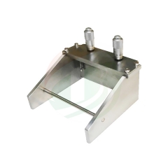
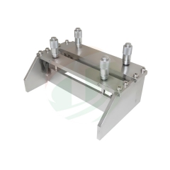
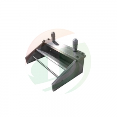
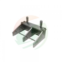
System layout The TOB-JYCM-250 consists of a rigid aluminium baseplate that carries a precision ground vacuum plate (L365 mm × W200 mm), a motorised linear stage with a push rod, and a mounting bracket for the slot die or alternative coating applicators. A stainless‑steel syringe (max. 60 ml) mounted on a syringe pump connects to the die head via PTFE tubing. The complete assembly is housed in a compact enclosure (L560 mm × W420 mm × H370 mm) that can be placed directly inside a glovebox.
Coating step by step
- Load the substrate: Place a pre‑cut sheet of aluminium or copper foil onto the vacuum plate, ensuring it covers the vacuum grooves. Switch on the vacuum pump; the foil is instantly pulled flat. The built‑in oil‑less pump holds the foil firmly even at coating speeds up to 20 mm/s.
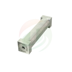
- Position the applicator: Mount the desired coating head—the standard configuration is the TOB‑JY100 slot die, but scraper blade, four‑side, or wire‑rod applicators can be interchanged. Position the applicator at the starting edge of the foil. The push rod, driven by the motorised stage, makes contact with the applicator.
- Prime the feed system: Fill the syringe with slurry, eliminating air bubbles by tapping or brief centrifugation. Insert it into the pump and purge the line until slurry appears at the die lip.
- Set coating parameters on the touch screen: Enter the coating speed (0.5–20 mm/s), syringe piston feed rate (0.05–5 mm/s), and stroke length (up to ≈ 250 mm, stepless). The speed and feed rate are independently controlled so that you can dial in the exact wet film thickness regardless of the slurry viscosity.
- Start coat: Press start. The motorised stage pushes the applicator at the set speed while the syringe pump extrudes slurry at the matched feed rate. The die lip spreads the slurry evenly across the foil width. Because the feed system is closed (syringe to die), there is no solvent evaporation during coating and minimal material waste—a small syringe can coat multiple electrode sheets.
- Drying: Immediately after the applicator reaches the end of the stroke, remove it and the push rod from the foil surface. Lower the heated cover over the wet film. Set the drying temperature (room temperature to 130 °C, ±1 °C) and timer via the digital controller. The large‑area heater ensures uniform drying across the entire foil, preventing edge cracking and solvent‑vapour concentration build‑up.
- Remove electrode: After drying, lift the cover, release the vacuum, and gently peel off the coated electrode. Reset the applicator and push rod to the home position for the next coat.
Control electronics A PLC with a touch‑screen interface orchestrates all motions. Because the coating drive and the syringe pump are motorised and digitally synchronised, the operator does not need to manually coordinate speed and feed—the system maintains a constant coating rate even as the syringe empties. Parameter adjustments, storage of up to 20 recipes, and fault diagnostics are all handled through the touch screen.
4. Key Engineering Advantages for Laboratory Electrode Coating
-
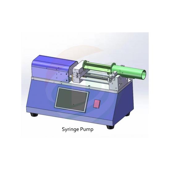
Syringe‑Pump Extrusion: Closed‑Loop, Low‑Waste Feeding
Unlike open‑reservoir doctor‑blade coaters where slurry is poured in front of the blade and exposed to air, the TOB-JYCM-250 uses a syringe pump to deliver slurry through a sealed line directly to the die lip. This eliminates solvent evaporation during coating—viscosity drift is virtually eliminated—and reduces slurry waste to less than 1 ml per run. For expensive high‑nickel cathode or silicon‑anode slurries, this directly saves on material cost. The piston feed rate (0.05–5 mm/s) is steplessly adjustable, making it possible to coat very thin films (a few microns wet) by using a slow feed and high coating speed. -
Integrated Vacuum Plate with Built‑In Pump
The L365 mm × W200 mm aluminium vacuum plate holds the foil perfectly flat without wrinkles, creases, or adhesive tape. Tape can leave residue, deform under heat, and create thickness variations. The oil‑less vacuum pump is built into the machine—no external vacuum source is needed—and the vacuum level can be adjusted to suit foil thickness and stiffness. This single feature dramatically improves coating uniformity compared to taping the foil to a bench. -
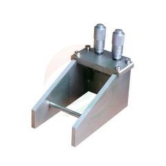
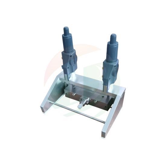
Multi‑Applicator Compatibility: Slot Die, Scraper Blade, Four‑Side,
Wire‑Rod
While the TOB‑JY100 slot die is the standard head, the machine accepts three other coating applicators: a scraper blade for low‑viscosity slurries, a four‑side film applicator that produces multiple wet film thicknesses in one stroke, and a wire‑wound rod for ultra‑thin coatings. Swapping applicators takes seconds and does not require recalibrating the stage. This flexibility allows a single machine to cover a wide range of slurry types—from thick anode coatings to thin solid‑electrolyte films—without purchasing separate coaters. A photo of the four applicator types is available on the product page for easy identification.
-
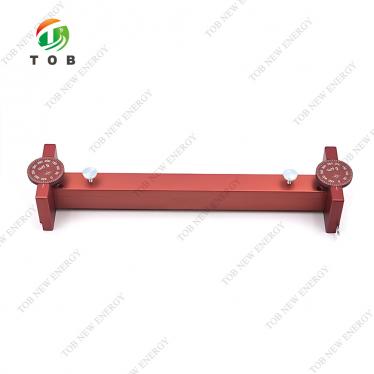
Precision Gap Control (±3 µm, Optional ±1 µm Digital Dial
Meter)
The coating gap—the distance between the die lip and the substrate—is the primary control for wet film thickness. The gap can be set between 0 and 5 mm using a micrometer dial with a standard accuracy of ±3 µm. An optional 1 µm digital dial meter further refines this adjustment for applications that demand extreme repeatability, such as multi‑layer solid‑state battery coatings. The ability to return to the same gap setting day after day removes the guesswork that plagues manually shimmed doctor blades. -
Heated Drying Cover with Uniform Temperature Control
After coating, a heated cover is placed over the wet film and the temperature is set digitally to any value between room temperature and 130 °C (±1 °C). The heater covers a large area equal to the vacuum plate, ensuring no cold spots that would cause uneven drying or residual solvent. The cover traps the heat while still allowing some ventilation to remove evaporated solvent. For NMP‑based slurries, this gentle, controlled drying prevents the sudden skinning that occurs when a wet film is placed directly into a hot oven, thereby reducing electrode cracking. -
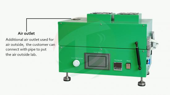
Glovebox‑Compatible, Compact Footprint
With external dimensions of L560 mm × W420 mm × H370 mm and a weight of 65 kg, the TOB‑JYCM‑250 fits on a standard laboratory bench or inside a moderate‑sized glovebox. The touch‑screen controller and all motion components are fully enclosed, and the vacuum pump exhaust can be routed out of the glovebox if required. For air‑sensitive materials like sulfide solid electrolytes, this means the entire coating process—from slurry loading to drying—can be conducted under an inert atmosphere. -
Motorised, Stepless Speed and Stroke Control
Coating speed (0.5–20 mm/s) and stroke length (up to ≈ 250 mm) are set digitally via the touch screen. Because the drive is a precision stepper or servo motor, the speed remains constant throughout the stroke, eliminating the manual variations that occur when pushing a blade by hand. This is particularly important for slurry systems that show shear‑thinning behaviour: a constant speed preserves a consistent shear history across the entire electrode, producing uniform microstructure.
5. Complete Technical Specifications
| Parameter | Specification |
| Model | TOB‑JYCM‑250 |
| Coating method | Slot die flat‑plate coating (standard TOB‑JY100 slot die); option for scraper blade, four‑side applicator, wire‑rod |
| Coating stroke | ≈ 250 mm, steplessly adjustable via touch screen |
| Coating drive | Motorised, speed steplessly adjustable |
| Coating speed | 0.5–20 mm/s |
| Substrate holding | Aluminium vacuum plate (L365 mm × W200 mm × H32 mm), built‑in oil‑less vacuum pump |
| Applicator gap adjustment | 0–5 mm, standard accuracy ±3 µm (optional 1 µm digital dial meter) |
| Feed system | Stainless‑steel syringe, max. 60 ml; closed‑loop delivery via PTFE tubing |
| Feeding speed (piston) | 0.05–5 mm/s, stepless adjustable |
| Drying system | Heated cover, room temperature to 130 °C, digital display controller, accuracy ±1 °C |
| Control | PLC with touch‑screen interface; parameter storage and recall |
| Power supply | AC 110–220 V, 50/60 Hz, single phase |
| Machine dimensions | L560 mm × W420 mm × H370 mm |
| Machine weight | Approx. 65 kg |
| Glovebox compatibility | Yes (compact size, enclosed components) |
6. Common Coating Defects and Practical
Troubleshooting
The table below draws on real issues
encountered during laboratory electrode coating and explains how the TOB‑JYCM‑250
helps prevent or resolve them.
| Defect | Likely Cause | How TOB‑JYCM‑250 Addresses It |
| Uneven coating thickness (thick at start, thin at end) | Manual blade speed inconsistent; slurry viscosity changes due to solvent evaporation. | Motorised coating drive at constant set speed (0.5–20 mm/s) eliminates speed variation. Closed syringe feed prevents solvent loss. Store a recipe for repeatable speed and feed. |
| Pinholes or craters | Dust on foil or air bubbles in slurry trapped under the die. | Vacuum plate holds foil clean and flat; the syringe feeding system can be pre‑purged to remove air. Degas the slurry in a vacuum mixer before filling the syringe. |
| Edge beads (thick ridges along coating edges) | Die width smaller than foil; slurry spreads laterally and accumulates. | Choose an applicator width slightly narrower than the foil. The motorised stroke length can be set to stop before the edge bead reaches the end of the foil. |
| Streaks or lines parallel to coating direction | Agglomerates lodged in the die lip or scratches on the die face. | The slot die and all applicators are easily disassembled for cleaning. After each use, flush with solvent and inspect the lip under a light. Polish with a lint‑free cloth. |
| Cracking during drying | Too‑fast solvent evaporation causing skinning; uneven temperature. | Use the heated cover with a two‑step temperature profile: 60 °C/5 min then ramp to 100–120 °C. The large‑area heater ensures uniform heat flux. |
| Delamination from current collector | Poor foil wettability; residual contamination from manufacturing. | Wipe foil with IPA and plasma‑treat if possible. The vacuum plate ensures intimate contact; a small initial priming layer can be coated at very low speed to improve adhesion. |
| Inconsistent dry loading between runs | Syringe piston speed not matched to coating speed; gap not reset to same value. | The stepless gap adjustment (±3 µm) and digitally set pump speed (0.05–5 mm/s) allow exact replication. Use the stored recipe function to recall parameters for each slurry type. |
7. Recommended Coating Parameters for
Common Electrode Formulations
These parameters are starting points
developed on a TOB‑JYCM‑250 with the standard slot die applicator (coating
width approximately 80–100 mm, depending on the die shim). All values assume
a slurry solid content of 45–50 % for NMP‑based systems and 40–45 % for aqueous
systems. Always calibrate with your actual slurry rheology.
| Electrode Material | Gap Setting (µm) | Coating Speed (mm/s) | Piston Feed Rate (mm/s) | Drying Profile | Notes |
| NMC622 cathode (PVDF/NMP) | 200 | 10 | 0.15 | 60 °C/5 min → 120 °C/15 min | Target ~2 mAh/cm² dry loading. Slurry viscosity ~5000 mPa·s. |
| LFP cathode (PVDF/NMP) | 250 | 8 | 0.2 | 60 °C/5 min → 110 °C/20 min | LFP slurries have higher solid content; reduce speed slightly to avoid dripping. |
| Graphite anode (CMC/SBR aqueous) | 150 | 15 | 0.12 | 80 °C/10 min → 120 °C/10 min | Aqueous slurries coat well at higher speed; ensure complete drying before removing. |
| Silicon‑graphite anode (PAA or CMC/SBR) | 180 | 8 | 0.18 | 60 °C/5 min → 100 °C/20 min | Higher binder content increases viscosity; use slow, controlled drying to avoid cracking. |
| Solid‑electrolyte interlayer (PVDF‑HFP/acetone) | 100 | 20 | 0.1 | Room temp. for 30 min, then 80 °C/10 min | Use the scraper blade applicator for very low‑viscosity solutions. |
8. Why Choose TOB‑JYCM‑250 Over a Basic
Manual Doctor‑Blade Setup: A Comparison
| Feature | TOB‑JYCM‑250 | Typical Manual Doctor Blade Coater |
| Coating drive | Motorised, constant speed (0.5–20 mm/s) | Hand‑drawn, operator‑dependent |
| Feed system | Syringe pump, closed, low waste | Open slurry pool, high solvent evaporation and waste |
| Substrate holding | Vacuum plate with built‑in pump | Tape or simple vacuum (if available) |
| Gap control | Micrometer dial, ±3 µm accuracy | Manual shims or feeler gauges, often ±10–20 µm |
| Integrated drying | Heated cover, up to 130 °C, ±1 °C | None—must transfer to separate oven |
| Parameter recording | Touch screen, up to 20 recipes | No recording; relies on notebook |
| Material changeover | Easy‑clean die and syringe | Blade and foil require thorough cleaning; high risk of cross‑contamination |
| Coating uniformity | High, consistent shear history | Variable, especially with thixotropic slurries |
| Glovebox use | Fully compatible | Manual operation difficult with gloves |
| Typical material waste per run | <1 ml | 2–5 ml (slurry left on blade/foil) |
Why researchers invest in the TOB‑JYCM‑250:
A hand‑coated electrode might look acceptable to the naked eye, but under SEM
its thickness can vary by ±15 %, and the dry loading from one coin cell to the
next may differ by 20 %. When you are trying to distinguish a 5 mAh/g
improvement in a new cathode material, that coating variability buries the real
signal in noise. The TOB‑JYCM‑250 eliminates that variability. Researchers who
move to automated slot die coating report tighter capacity data, fewer outlier
cells, and clearer trends—saving months of repeated experiments. The integrated
drying and glovebox compatibility further streamline the workflow, turning a
multi‑step manual process into a single, clean, documented operation.
9. Engineering FAQ — Desktop Slot Die
Coating for Battery Electrodes
Q1: How do I clean the slot die head
after coating a viscous NMP‑based cathode slurry?
Immediately after coating, detach the die from the mount and remove the shim
(if applicable). Flush the die and all tubing with clean NMP using the syringe
pump at full piston speed (5 mm/s). Collect the waste NMP—do not pour it down
the drain. Wipe the die lip with a soft cloth soaked in NMP, never with metal
tools. If slurry has dried inside the die channel, soak the entire die in NMP
overnight. The stainless‑steel construction tolerates this without corrosion. A
clean die is essential for the next coating; even a microscopic dried particle
can create a streak.
Q2: Can I use this machine with aqueous
slurries (e.g., graphite/CMC/SBR)?
Yes. All wetted parts—syringe, tubing, die head—are stainless steel or PTFE,
which are compatible with water. However, after coating aqueous slurries, you
must thoroughly dry the system before storing, as residual water can promote
corrosion long‑term. Flush with pure water, then with isopropyl alcohol to
displace the water, and finally blow dry with compressed air. The heated drying
cover can be used to dry the vacuum plate after cleaning.
Q3: How do I know if the syringe piston
feed rate is matching the coating speed to get my target wet thickness?
A simple check: place a piece of foil, start the coating, and observe the bead
of slurry at the die lip. If the bead grows larger as coating proceeds, the
feed rate is too high and you are accumulating excess slurry; if the bead
shrinks and the die runs dry, the feed rate is too low. Adjust the piston speed
in small increments (0.01–0.05 mm/s) until the bead remains a constant 1–2 mm
in diameter throughout the stroke. Once found, save this combination in a
recipe for that specific slurry.
Q4: The foil sometimes curls or lifts at
the edges during coating—why, and what can I do?
Very thin foils (8–12 µm) can lift if the vacuum is insufficient or if the foil
was not perfectly flat to begin with. First, ensure the vacuum plate surface is
clean and free of dried slurry particles. If the foil still lifts, increase the
vacuum level slightly (if your unit has adjustable bleed). For extremely thin
copper foils, you can lightly tape the very edges outside the coating area, but
this should be a last resort—the vacuum system is designed to hold without tape
for foils down to 10 µm. Another tip: place a weight on the foil leading edge
before pulling vacuum, then remove it once the foil is held.
Related Machine:
◉ TOB-ZCB-01 - TOB-ZCB-01 This piston pump is designed for the battery slurry slot die coating machine. It feeds the battery slurry to the slot die applicator.
◉ TOB-VFC-150 - TOB-VFC-150 Film coating machine with dryer for battery electrode coating. Integrated heating system up to 130°C, ideal for coin cell and pouch cell lab research.
◉ TOB-JYCM-800 - TOB-JYCM-800 is a laboratory-scale slot die coating system designed for precision thin-film coating research, especially for lithium battery electrode coating, solar photovoltaic films, OLED materials, and polymer conductive coatings.
Tired of inconsistent hand‑coated electrodes masking your material's true performance? Contact our coating application engineers. We'll help you select the right applicator for your slurry type and provide a starting‑point parameter sheet for your specific electrode formulation.
tob.amy@tobmachine.com | +86 181 2071 5609
Previous:
Lab Slot Die Coater with 800mm Stroke For Battery Electrode CoatingNext:
Lab Dip Coater Film Coating Machine
If you are interested in our products and want to know more details,please leave a message here,we will reply you as soon as we can.