- Home
- >
Batteries for Sale
- >
Sodium-ion Batteries
- >
18650 Sodium ion Batteries for Sale
Categories
Hot Products
Loading...

18650 Sodium ion Batteries for Sale
Brand:
TOB NEW ENERGYitem no.:
TOB-18650-C-Naorder(moq):
1Payment:
L/C, T/Tproduct origin:
Chinashipping port:
XIAMEN
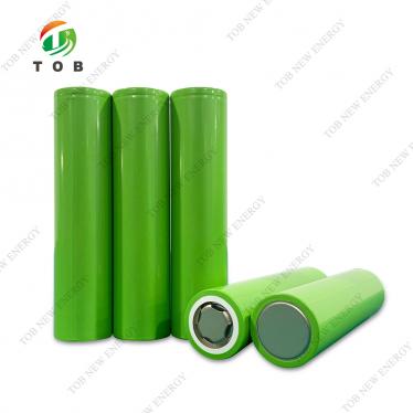
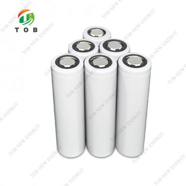
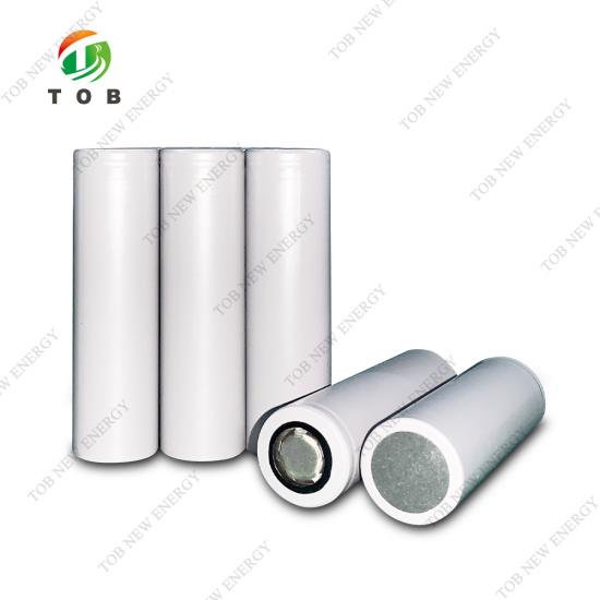
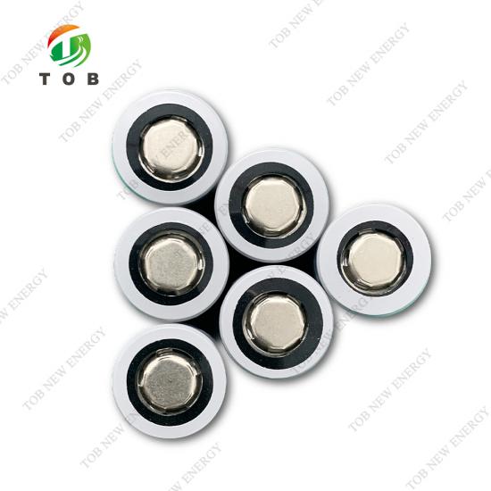
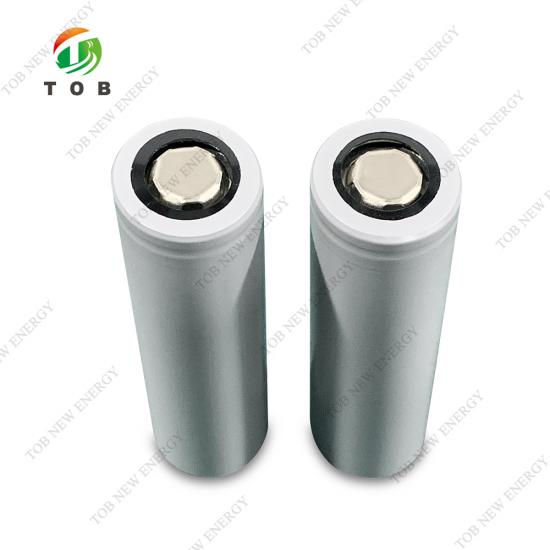
18650 Sodium-ion Battery Cell 1300mAh 3.05V | TOB-18650-C-Na
Product Overview and Ideal Applications
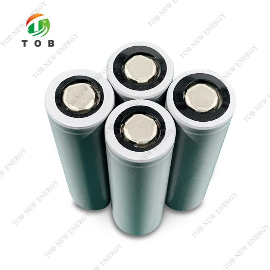
The 18650 sodium‑ion battery is a cylindrical rechargeable cell that uses sodium ions as charge carriers instead of lithium. TOB‑18650‑C‑Na delivers a nominal voltage of 3.05 V and a rated capacity of 1300 mAh, providing a drop‑in form‑factor compatible with existing 18650 pack designs while offering several inherent advantages: sodium is abundant and low‑cost, the cell operates reliably from –40 °C to +60 °C during discharge, and its safety performance under abuse conditions (overcharge, short circuit, crush, heating) is outstanding, with no fire or explosion in standard certification tests.
Unlike lithium‑ion cells that require careful shipping at partial state‑of‑charge and face restrictions on air transport, sodium‑ion cells can be discharged to 1.8 V and stored safely, simplifying logistics. The cell’s weight of 36.5 g and standard dimensions (65.2 mm length, 18.35 mm diameter) allow direct replacement of standard 18650 lithium cells in many applications, enabling a seamless transition to a more sustainable, lower‑cost chemistry.
Ideal for:
- Stationary energy storage systems (ESS) requiring thousands of cycles, wide temperature tolerance, and intrinsic safety.
- Low‑speed electric vehicles, e‑bikes, and e‑scooters where cost and safety outweigh the need for maximum energy density.
- Backup power, telecom base stations, and UPS systems that must operate reliably across a broad temperature range.
- Power tool and garden tool battery packs where high discharge rates (up to 7800 mA) and mechanical robustness are required.
- Any manufacturer transitioning from lithium‑ion to sodium‑ion for regulatory compliance, supply chain security, or total‑cost‑of‑ownership reduction.

Where Sodium‑Ion 18650 Cells Fit in Battery Pack Design
The TOB‑18650‑C‑Na is a direct replacement for 18650 lithium‑ion cells in most multi‑cell series‑parallel configurations. Because its nominal voltage is 3.05 V (vs. 3.6 V for NMC or 3.2 V for LFP), a 10S sodium‑ion pack will deliver approximately 30.5 V, whereas a 10S lithium‑ion pack typically delivers 36 V. This voltage difference is small enough to be accommodated by minor adjustments to the battery management system (BMS) voltage thresholds and the motor controller’s input range.
The cell’s discharge curve is relatively flat between 3.0 V and 2.0 V, delivering over 95 % of its rated capacity within this window. The end‑of‑discharge voltage of 1.8 V is well below the typical lithium‑ion cutoff (2.5 V), but this deep‑discharge capability is a defining feature of sodium‑ion chemistry: the cell can be fully discharged for storage without damage, which eliminates the “sleep mode” degradation seen in lithium cells kept at low voltage.
Key electrical characteristics relevant to pack design:
- Maximum continuous discharge current: 7800 mA (approximately 6 C based on 1300 mAh) at 25 °C. This high rate capability makes the cell suitable for power‑intensive applications.
- Standard charge method: CC‑CV, 650 mA to 3.95 V, with a 65 mA cut‑off. The charge temperature range (–20 °C to +55 °C) is notably wider than most lithium cells, simplifying thermal management in outdoor applications.
- AC impedance: ≤30 mΩ, ensuring low internal losses and minimal heating during high‑rate discharge.
Electrical and Safety Performance — Why Sodium‑Ion Excels
Capacity and Energy Density
At first glance, a 1300 mAh cell with a 3.05 V nominal voltage appears to offer a lower energy density than an equivalent 18650 lithium cell (typ. 2600 mAh, 3.6 V). However, sodium‑ion cells are not intended to compete on gravimetric energy density alone. Their value lies in a combination of factors: the raw material cost per kWh is lower; the safety margin is higher, reducing the need for expensive pack‑level protection; and the wide temperature range eliminates auxiliary heating or cooling, which in turn improves system‑level energy density because fewer parasitic loads are needed.
Cycle Life
The standard cycle life test (0.5 C charge to 3.9 V, 0.5 C discharge to 2.0 V, 25 °C) yields ≥1000 cycles before the capacity drops below 80 % of the nominal value. This is competitive with LFP lithium‑ion cells, particularly considering that the sodium cell achieves this without cobalt or nickel.
Low‑ and High‑Temperature Performance
- –20 °C discharge at 1 C: >80 % of nominal capacity. This is a game‑changer for outdoor energy storage in cold climates where lithium cells require pre‑heating.
- +55 °C discharge at 1 C: >95 % of nominal capacity, demonstrating thermal stability.
Safety Performance
The cell has passed the following abuse tests according to the manufacturer’s specifications, all with the criterion “No Fire, No Explosion”:
| Test | Condition | Result |
| Overcharge | 1C to 5.5 V or 60 min | No fire, no explosion |
| Low pressure (11.6 kPa) | 6 h at vacuum, 23 °C | OCV ≥90 % of initial |
| Heating | 5 °C/min to 130 °C, 30 min | No fire, no explosion |
| Temperature cycling | –40 °C ⇄ +75 °C, 10 cycles | No fire, no explosion |
| External short | 80 mΩ, 24 h | Max surface temp. ≤150 °C |
| Forced discharge | 1300 mA reverse charge, ≥90 min | No fire, no explosion |
Mechanical integrity tests (shock, crush, free drop) are also passed without fire or explosion, and the open‑circuit voltage after shock testing remains ≥90 % of the pre‑test value. This level of safety is a direct consequence of the sodium‑ion chemistry, which is inherently less prone to thermal runaway than high‑nickel lithium chemistries.
Key Engineering Advantages of TOB-18650-C-Na
Wide Operating Temperature Range (–40 °C to +60 °C Discharge)
The cell can be discharged at –40 °C without the capacity loss that cripples conventional lithium cells. This eliminates the need for battery heaters in outdoor cabinets, reducing system cost and complexity. Charging is permitted down to –20 °C, which covers most real‑world winter conditions.
Inherent Safety — No Thermal Runaway
All abuse tests (overcharge, heating to 130 °C, short circuit, crush, nail penetration proxy tests) are passed without fire or explosion. This inherent safety simplifies pack design: fewer protective devices, smaller cell‑to‑cell spacing, and potentially lighter enclosure materials, all contributing to a higher pack‑level energy density and lower cost.
1000+ Cycle Life Under Standard Conditions
More than 1000 cycles to 80 % capacity at 0.5 C cycling is competitive with commercial LFP cells. The sodium‑ion chemistry does not suffer from the same manganese dissolution or metal‑dendrite mechanisms that limit some lithium chemistries, leading to a predictable, gradual capacity fade that is easy to model for warranty forecasting.
Drop‑In 18650 Form Factor
The cell dimensions (65.2 mm × 18.35 mm) and weight (36.5 g) are within the standard 18650 envelope, allowing it to be used in existing holders, fixtures, and spot‑welding jigs without modification. This zero‑change mechanical integration accelerates the transition from lithium to sodium.
Deep Discharge to 1.8 V Without Damage
Unlike lithium cells that degrade if discharged below 2.0 V, the TOB‑18650‑C‑Na can be fully discharged to 1.8 V and stored for extended periods without copper dissolution or SEI damage. This makes it ideal for seasonal applications (e.g., agricultural sensors, marine buoys) and for shipping compliance—the cell can be transported at a completely discharged state, classified as non‑hazardous under many regulations.
Low Internal Resistance (≤30 mΩ)
The AC impedance of ≤30 mΩ ensures that the cell generates minimal internal heat during high‑rate discharge, and the voltage sag under load is small. This is important for power‑tool packs where the peak current can approach the maximum of 7800 mA.
Complete Technical Specifications
General Specifications
| No. | Item | Specification |
| 1 | Limited Charge Voltage | 3.95V |
| 2 | Nominal Voltage | 3.05V |
| 3 | Rated Capacity (0.2C) | 1300mAh |
| 4 | Standard Charging Current | 650mA |
| 5 | Max Charge Current | 1300mA |
| 6 | Standard Discharging Current | 650mA |
| 7 | Max Discharge Current | Under the conditions of 25℃±2℃, discharging at 7800mA at 100% SOC |
| 8 | Discharge End Voltage | 1.8V |
| 9 | Operating Temperature(Cell Surface temperature) | Charging: -20℃~ 55℃, 65%±20%RH Discharging: -40℃~ 60℃, 65%±20%RH |
| 10 | Storage Temperature | 15℃~ 35℃ |
| 11 | Cell Weight | 36.5g±0.5g |
| 12 | AC Impedance | ≤30mΩ |
| 13 | Cell Dimensions (for shipping state) |
Length: 65.2mm±0.2mm Diameter: 18.35mm±0.15mm |
Standard test conditions
Unless otherwise specified, all tests stated in this Product Specification are conducted at below conditions:
- Temperature :23℃±2℃
- Relative Humidity :65%±20%
- Atmospheric Pressure:86kPa~106kPa
Electrical characteristics
|
No. |
Items |
Test Methods and Conditions |
Criteria |
|
1 |
Standard |
Charging the cell with constant current at 650mA and then with constant voltage at3.95V. |
Limited Charge |
|
2 |
Rapid |
Charging the cell with constant current at 1300mA and then with constant voltage at3.95V till charge current declines to≤65mA. |
Limited Charge Voltage = 3.95V |
|
3 |
Standard Discharge |
The capacity means the discharge capacity of the cell, which is measured
with discharge current of 0.5C with 1.8V cut-off voltage after standard |
Discharge Voltage =1.8V |
|
4 |
Initial Impedance |
Internal resistance measured at AC 1KHz within 1 hour after standard charge. |
≤30mΩ |
|
5 |
Cell Voltage |
Cell state upon shipment |
2.5-3.0V |
|
6 |
Capacity |
(1)Prior to charging, the cell shall be discharged at a constant current
of 0.5C down to the cut off discharge voltage 1.8V, rest for 10 minutes. |
≥1300mAh |
|
7 |
Rate Discharge |
(1)Prior to
charging, the cell shall be discharged at a constant current of 0.5C down to
cutoff discharge voltage 1.8V,rest for 10 minutes. |
≥98% Nominal capacity |
|
8 |
Low Temperature |
(1) The cell
shall be charged in accordance with the standard charge. |
discharge capacity≥80 |
|
9 |
High Temperature |
(1) The cell
shall be charged in accordance with the standard charge. |
discharge capacity≥95% |
|
10 |
Charge Retention and |
After the cell is fully charged according to the standard method, it is
stored at 25℃ ±2℃for 30 days, and then discharged at 0.5C at 25℃ ±2℃until the discharge termination
voltage is 1.8V. This discharge capacity is maintained by charge. After the
cell is recharged, the cell is |
Capacity Retention≥90% |
|
11 |
Standard Cycle Life |
Temperature : 25°C±2°C |
≥1000cycles |
Cell Safety Tests
|
No. |
Items |
Test Methods and Conditions |
Criteria |
|
1 |
Overcharge Test |
After standard charge, the cell shall be charged at 1C with cutoff voltage 5.5V or charging time reached 60min, observe 1h (one of the conditions is preferred to stop test). |
No Fire, No Explosion. |
|
2 |
Low Pressure Test |
The full charged cells are to be stored for at least 6h at an vacuum environment with pressure of less than 11.6kPa, and temperature of 23℃±2℃. |
No Fire, No Explosion. |
|
3 |
Heating Test |
The cells are fully charged with standard charging method, and put into oven with nature air or cycled air convected, heat cell by velocity of 5℃/min±2℃/min to 130℃±2℃,and maintain for 30 minutes. |
No Fire, No Explosion. |
|
4 |
Temperature Cycling Test |
The fully charged cells are placed in a test chamber and subjected to
the following cycles: |
No Fire, No Explosion. |
|
5 |
Short Test |
The fully charged cells are placed in a test chamber and subjected to the following cycles: short the positive and negative terminals with wire resistance of 80mΩ±20mΩ.Tests are to be conducted at standard test conditions, keep 24h or surface temperature decline to 20% of max. temperature, test is end. |
No Fire, No Explosion. |
|
6 |
Forced Discharge |
The cell is discharged with standard discharging method. Inverse charge current =1300mA time:≥90minutes |
No Fire, No Explosion. |
Mechanical Tests
|
No. |
Items |
Test Methods and Conditions |
Criteria |
|
1 |
Shock Test |
The full charged cell is fixed on shock table. Each cell shall be subjected to a half-sine shock of peak acceleration of 150 gn and pulse duration of 6 milliseconds. Each cell shall be subjected to three shocks in the positive direction by three shocks in the negative direction of three mutually perpendicular mounting positions of the cell for a total of 18 shocks. |
No Fire, No Explosion. |
|
2 |
Crush Test |
A cell is crushed between two flat surfaces. The applied force is 13 kN±1kN by hydro cylinder. Once the maximum pressure has been obtained, or voltage decrease to 1/3 of nominal voltage sharply, or 10% of deformation has occurred compared |
No Fire, No Explosion. |
|
3 |
Free Drop Test |
The fully charged cell drops on the concrete ground from 1m height, total 3 times, to obtain the shock of random directions. After the test, the cell shall rest for a minimum of one hour and then a visual inspection shall be performed. |
No Fire, No Explosion. |
Visual inspection
There shall be no such defect as scratch, flaw, crack, and leakage, which may adversely affect commercial value of the cell.

Common Questions for Pack Designers
Q1: What BMS voltage thresholds should I use for a 10S sodium‑ion pack?
For a 10S configuration, the recommended settings are:
- Charge voltage limit: 39.5 V (10 × 3.95 V)
- Float voltage: 39.0 V (10 × 3.90 V)
- Discharge cut‑off: 18.0 V (10 × 1.8 V) or slightly higher at 20 V to extend cycle life. Because the cell can be deeply discharged, you may set the warning at 22 V and the shutdown at 20 V. Ensure the BMS balancing current is appropriate for the 650 mA standard charge rate; passive balancing at 50–100 mA is typical.
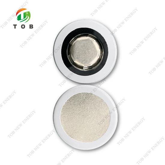
Q2: Can I spot‑weld nickel strips directly to this cell like I do with lithium 18650 cells?
Yes. The cell casing is standard nickel‑plated steel, fully compatible with resistance spot welding. Use the same welding parameters you would for a low‑impedance lithium cell: 2–3 ms pulse, moderate pressure, and ensure the weld tips are clean. The cell’s AC impedance of ≤30 mΩ is similar to many high‑power lithium cells, so the weld current should be in the typical range. Always perform a peel test on the first samples.
Q3: How should I store these cells for long periods?
Store at 15 °C to 35 °C with the cell voltage at 2.5–3.0 V (the shipping state). For storage longer than 6 months, check the voltage every 3 months. If the voltage drops below 2.0 V, recharge to 2.5 V. The cell can be stored fully discharged (1.8 V) for transport without damage, but for long‑term storage, the mid‑voltage range is optimal to preserve cycle life.
Q4: Is the capacity test result of 1300 mAh guaranteed for every cell?
The rated capacity is 1300 mAh at 0.2 C discharge. The specification allows up to 3 repeat tests if the initial result is below 1300 mAh, indicating that the cell needs full formation cycling to reach maximum capacity. In production runs, the capacity distribution is tightly controlled, but individual cells out of the box may measure slightly lower until properly cycled.
Q5: Can this cell be used in series strings without a BMS?
No. As with any lithium‑based chemistry, series strings require a BMS to prevent over‑charge and over‑discharge of individual cells. Although the sodium‑ion cell is more tolerant to abuse, a BMS is essential for safety and longevity. The BMS should monitor voltage and temperature per cell, especially in packs exposed to the wide operating temperature range this cell supports.
Ready to build a lower‑cost, safer, and temperature‑resilient battery pack? Request a quotation for TOB‑18650‑C‑Na cells, or order evaluation samples to test in your own application. Our application engineers can also assist you with BMS selection and pack design review.
tob.amy@tobmachine.com | +86 181 2071 5609
You May Also Need
- Battery Materials — From cathode and anode active powders to current collector foils, electrolytes, and binders, we supply key materials for lithium‑ion, sodium‑ion, and solid‑state battery R&D. Find the right precursor or electrode component for your cell chemistry.
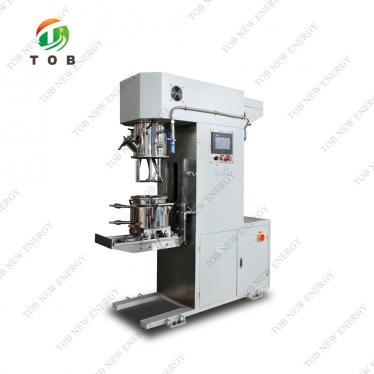
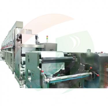
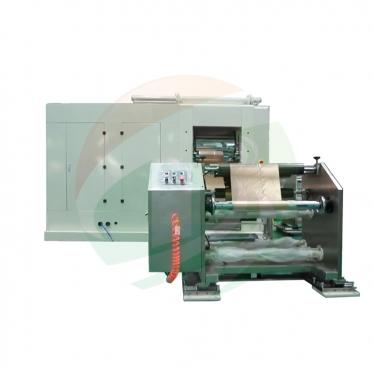
- Electrode Preparation — Mix, coat, calender, and dry your electrode films with our lab‑scale and pilot‑scale equipment. Whether you are working with wet‑process slurries or dry‑process powders, our mixers, coaters, and roller presses ensure uniform, reproducible electrodes.
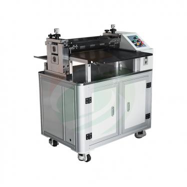
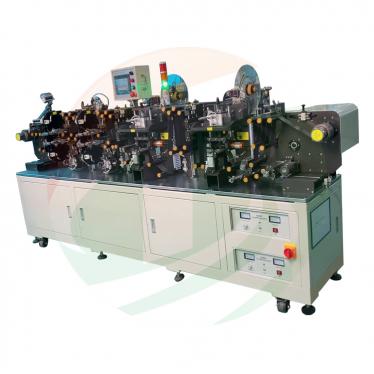
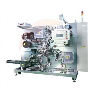
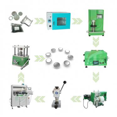
- Battery Production Line — Build cells and packs efficiently with our automated assembly, welding, and testing systems. From manual coin‑cell crimpers to AI‑driven double‑side spot welders, we provide the equipment that turns materials into finished, test‑ready batteries.
If you are interested in our products and want to know more details,please leave a message here,we will reply you as soon as we can.