
Categories
new blog
- A Technical Roadmap from Battery Lab Line and Pilot Line to Full-Scale Battery Production Line Solutions
- TOB NEW ENERGY: China Integrated Battery Solutions Supplier Equipment and Materials to Turnkey Production Lines
- TOB Senior Engineer Appointed CSU Industry Graduate Mentor
- Solid-State Battery Manufacturing Equipment Guide 2026–2027
- Supercapacitors vs Batteries: Complementary Industrial Energy Storage
Tags
F-doped Carbon Coated Nano-Si Anode with High Capacity
F-doped Carbon Coated Nano-Si Anode with High Capacity: Preparation by Gaseous Fluorination and Performance for Lithium Storage
Author: SU Nan, QIU Jieshan, WANG Zhiyu. F-doped Carbon Coated Nano-Si Anode with High Capacity: Preparation by Gaseous Fluorination and Performance for Lithium Storage. Journal of Inorganic Materials, 2023, 38(8): 947-953 DOI:10.15541/jim20230009
Abstract
Si anodes hold immense potential in developing high-energy Li-ion batteries. But fast failure due to huge volume change upon Li uptake impedes their application. This work reports a facile yet low-toxic gas fluorination way for yielding F-doped carbon-coated nano-Si anode materials. Coating of nano-Si with F-doped carbon containing high defects can effectively protect Si from huge volume change upon Li storage while facilitating Li+ transport and formation of stable LiF-rich solid electrolyte interphase (SEI). This anode exhibits high capacities of 1540-580 mAh·g-1 at various current rates of 0.2-5.0 A·g-1, while retaining >75% capacity after 200 cycles. This method also addresses the issues of high cost and toxicity of traditional fluorination techniques that use fluorine sources such as XeF2 and F2.
Keywords: Li-ion battery; Si anode; F-doped carbon; gaseous fluorination method
Developing efficient energy storage and conversion technologies will help achieve the goal of “carbon peaking and carbon neutrality”. Lithium-ion batteries are currently one of the most widely used high-efficiency energy storage technologies [1]. However, commercial graphite anodes have low lithium storage capacity, which greatly limits the energy density of lithium-ion batteries [2]. Silicon has the advantages of low potential and abundant reserves, and its theoretical specific capacity (4200 mAh·g-1) is much higher than that of graphite anode, so it is regarded as a candidate anode material to replace graphite [3]. Silicon materials achieve lithium storage based on the reversible alloying reaction with lithium ions, but this process is accompanied by huge volume changes (~400%), which leads to rapid powdering and failure of the electrode, becoming a key bottleneck restricting the practical application of silicon anodes [3- 4].
In recent years, researchers have developed a variety of strategies to improve the stability and electrochemical performance of silicon anodes. Such as: nanometerization [5], structural composite with conductive carbon and other materials [6-7], etc. Improve the structural stability of the silicon anode by alleviating the mechanical stress associated with the volume expansion of lithium storage at the microscopic scale. Develop new electrolytes or electrolyte additives to improve the stability and Coulombic efficiency of the solid electrolyte interface phase (SEI) on the surface of the silicon anode [8]. Develop efficient polymer binders (such as sodium carboxymethyl cellulose, sodium alginate, polyacrylic acid-based polyrotaxane [9], etc.). Strengthen the bonding force between active materials, between active materials and conductive network, and between electrode film and current collector [9-10]. Among them, carbon coating is one of the most effective means to improve the structural stability of silicon anodes and modulate surface and interface properties [3-4,11]. However, the tightly coated highly stable carbon layer also hinders lithium ion transport and limits the full performance of the silicon anode.
In addition, the repeated volume changes of the silicon anode during the continuous charge and discharge process also cause the SEI film to continuously break and grow repeatedly, resulting in the continuous loss of active lithium and electrolyte on the electrode surface [12]. In response to the above problems, this study proposes an efficient gas-phase fluorination method to coat the surface of the silicon anode material with a highly defective amorphous carbon layer rich in fluorine elements to improve its structure and interface stability. Compared with traditional fluorination technology that uses high-cost and highly toxic fluorine sources such as XeF2 or F2 [13], this strategy is simpler and less toxic. The fluorine-doped carbon layer coating the surface of nano-silicon materials can effectively buffer the volume expansion of lithium-embedded silicon anodes while improving lithium ion transport capabilities. And a highly stable SEI film rich in inorganic fluoride is constructed in situ to achieve the goal of improving the cycle stability of the silicon anode.
1 Experimental method
1.1 Material preparation
Preparation of carbon-coated nano-silicon (Si@C):0.3 g of commercial nanosilica powder (particle size 20~100 nm, Aladdin's reagent) was ultrasonically dispersed in 28 mL of a mixed solvent of deionized water and ethanol (volume ratio 5:2). After adding 0.4 mL of 3-aminopropyltriethoxysilane, stir for 2 h to form a uniform dispersion A. Dissolve 0.115 g of 4,4-dihydroxydiphenyl sulfide and 0.1 g of 3-aminophenol in 28 mL of a mixed solvent of deionized water and ethanol (volume ratio 5:2) to form a homogeneous solution B. Mix dispersion A and solution B evenly, add 0.1 mL ammonia water, stir for 30 min, then add 0.14 mL formaldehyde solution (37%~40%), and react with constant stirring at 30 °C for 12 h. After the reaction, the phenolic resin-coated nanosilica (Si@AF) was obtained by centrifuging and washing with ethanol and deionized water alternately three times. It was calcined in argon gas at 800 °C for 3 h to obtain carbon-coated nano-silicon (Si@C).
Preparation of fluorine-doped carbon-coated nano-silicon (Si@C-F):100 mg Si@C and 200 mg polyvinylidene fluoride (PVDF) were placed in an argon-protected tube furnace. The quartz boat containing PVDF is located upstream of the air flow, and the quartz boat containing Si@C is located downstream of the air flow. It is roasted at 600 °C for 3 h to obtain fluorine-doped carbon-coated nano-silicon (Si@C-F).
1.2 Battery assembly and electrochemical performance testing
1.2.1 Battery assembly
Assemble the CR2016 button battery for testing. Mix the active material, conductive carbon black and carboxymethylcellulose sodium binder evenly in a mass ratio of 7:2:1. Deionized water was added as the solvent and dispersant, and the obtained slurry was evenly coated on the copper foil as the working electrode. The active material loading was 0.8~1.0 mg·cm-2. Metal lithium sheets were used as counter electrodes and reference electrodes. The electrolyte is a DOL/DME solution dissolved in 1.0 mol/L LiTFSI (lithium bistrifluoromethanesulfonate imide) and 2.0% LiNO3(DOL is 1, 3-dioxolane, DME is ethylene glycol dimethyl ether, volume ratio 1:1). Assemble the cell in an argon-filled glove box (water content < 0.1 μL/L, oxygen content < 0.1 μL/L).
1.2.2 Battery performance test
Use the IVIUM Vertex.C.EIS electrochemical workstation to analyze the reaction mechanism and reaction kinetics of the battery using the Cyclic Voltammetry (CV) method. The voltage range is 0.01~1.5 V, and the sweep rate is 0.05~0.5 mV·s- 1. Electrochemical Impedance Spectroscopy (EIS) was used to analyze electrode dynamics. The test frequency range was 100 kHz~10 mHz, and the disturbance voltage amplitude was 5.0 mV. Land CT2001A battery tester was used to study the lithium storage performance using the constant current charge and discharge method. The voltage window was 0.01~1.5 V (vs. Li/Li+), and the current density was 0.2~5.0 A·g-1.
2 Results and discussion
2.1 Analysis of appearance, structure and composition of materials
The preparation process of fluorine-doped carbon-coated nano-silicon materials is shown in Figure 1. First, polymer-coated silicon nanoparticles (Si@AF) are prepared based on phenol-aldehyde condensation polymerization reaction and converted into amorphous carbon-coated nano-silicon nanoparticles (Si@C) at high temperature. Then polyvinylidene fluoride is used as the fluorine source, and fluorine is doped into the carbon layer outside the silicon nanoparticles through the gas phase fluorination method at high temperature. Figure 2(a) shows the XRD patterns of Si@C and Si@C-F materials. Diffraction peaks located at 2θ=28°, 47°, 56°, 69° and 76°. They correspond to the (111), (220), (311), (400) and (331) crystal planes of single crystal silicon (JCPDS 77-2108) respectively. The broad peak located at 2θ=25°~26° is attributed to the short-range ordered carbon structure formed by the carbonization of the phenolic condensation polymerization product. The carbon coating layer with high conductivity and excellent structural flexibility can effectively alleviate the pulverization failure of silicon materials during the charge and discharge process and improve the conductivity of the electrode. Figure 2(b) is the Raman spectrum of Si@C and Si@C-F materials, with obvious absorption peaks appearing at 515, 947, 1350 and 1594 cm-1. Among them, the absorption peaks at 515 and 947 cm-1 are the characteristic peaks of crystalline silicon, which are derived from the first-order photophonon scattering and the second-order transverse photophonon scattering of silicon respectively [14]. The absorption peaks at 1350 and 1594 cm-1 correspond to the aromatic carbon configuration stretching vibration (G mode) and the disordered defect carbon structure (D mode), respectively. Generally speaking, the intensity ratio of D mode and G mode (ID/IG) can be used to measure the degree of defects and disorder of carbon materials [15]. Compared with Si@C material (ID/IG=0.99), the ID/IG of Si@C-F material increases to 1.08. It shows that the fluorination process can increase the defects of the carbon coating layer, which is beneficial to tightly coating nano-silicon while improving lithium ion transport capabilities.
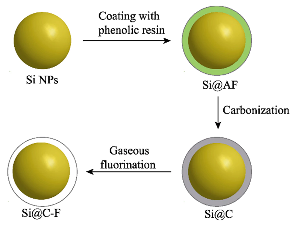
Fig. 1 Schematic illustration of the production of Si@C-F
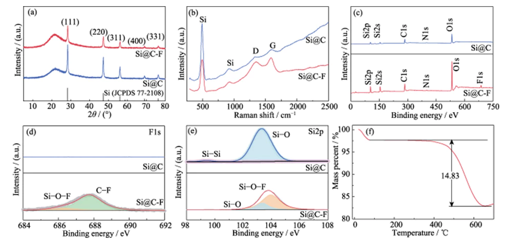
Fig. 2 (a) XRD patterns, (b) Raman spectra, (c) XPS survey scan, (d) high-resolution F1s and (e) Si2p XPS spectra of Si@C and Si@C-F, (f) TGA curve of Si@C-F
The XPS full spectrum shows that the Si@C material contains O, N, C, and Si elements (Figure 2(c)). The atomic fraction of F element in the Si@C-F material obtained after fluorination treatment is approximately 1.8%. In the high-resolution F1s XPS spectrum (Figure 2(d)), the two characteristic peaks at the binding energy of 686.3 and 687.8 eV correspond to C-F and Si-O-F respectively, and C-F is the dominant one. It shows that the fluorination treatment successfully introduced fluorine element into the amorphous carbon layer coated on the surface of nano-silicon. The high-resolution Si2p (Figure 2(e)) and F1s XPS spectra prove that Si atoms interact chemically with the F element in the carbon layer by forming Si-O-F bonds, which is beneficial to the tight coating of the carbon layer on the silicon surface. Thermogravimetric analysis (TGA) shows that the mass fraction of Si in the Si@C-F material is approximately 85.17% (Figure 2(f)).
SEM analysis shows that the Si@C-F material is composed of nanoparticles with a size of <100 nm (Figure 3(a~c)). After high-temperature carbonization and gas-phase fluorination treatment, the carbon material is still uniformly coated on the surface of the silicon nanoparticles.
Fig. 3 (a-c) SEM images, (d-f) TEM images and (g-i) elemental mapping of Si@C-F
TEM analysis shows that the silicon nanoparticles are completely and evenly coated in a carbon layer with a thickness of about ten nanometers, forming a core-shell structure (Figure 3(d~e)). Silicon nanoparticles have a single crystal structure, in which the lattice spacing of 0.328 nm corresponds to the (111) crystal plane of Si, and the fluorine-doped carbon layer covering it has an amorphous structure (Figure 3(f)). The element distribution spectrum proves that C and Si elements are evenly distributed in Si@C-F (Figure 3(g~i)).
2.2 Electrochemical properties of materials
Figure 4(a, b) is the CV curve of Si@C and Si@C-F anode materials. The sweep speed is 0.1 mV·s-1 and the voltage range is 0.01~1.5 V. In the first cycle, the weak broad peak in the range of 0.1~0.4 V corresponds to the irreversible process of electrolyte decomposition to form an SEI film; the reduction peak at 0.01 V corresponds to the process of crystalline silicon forming silicon-lithium alloy (LixSi) through alloying reaction. During the subsequent charging process, the two oxidation peaks at 0.32 and 0.49 V correspond to the process of dealloying of LixSi to form amorphous silicon [16]. Fluorination treatment can achieve structural doping and etching effects. A large number of structural defects are introduced into the amorphous carbon layer coated on the surface of the Si material to form a three-dimensional lithium ion transport channel, accelerate lithium ion transport and enhance the electrochemical reactivity of the Si material. Therefore, Si@C-F exhibits a sharper delithiation oxidation peak at 0.49 V than the Si@C anode without fluorine doping. During the subsequent discharge process, the new reduction peak at 0.19 V corresponds to the lithium insertion process of amorphous silicon formed during the first charging process [16-17]. As the number of cycles increases, the positions of the oxidation peak and the reduction peak in the CV curve no longer change, indicating that Si@C and Si@C-F anode materials follow a similar alloying lithium storage mechanism after the first charge and discharge. During this process, the oxidation peak and reduction peak gradually increased, reflecting a typical electrode activation process.
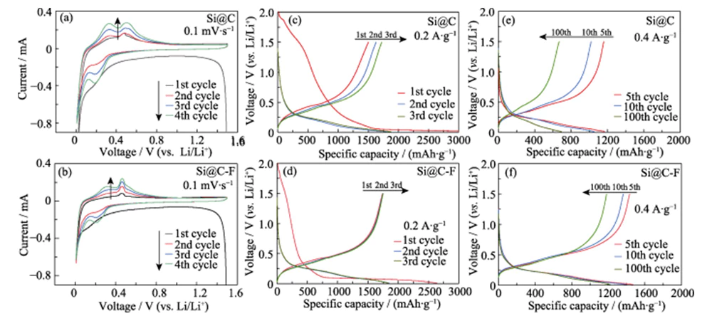
Fig. 4 (a, b) CV curves at a scan rate of 0.1 mV·s-1 and charge-discharge voltage curves at (c, d) 0.2 and (e, f) 0.4 A·g-1 for (a, c, e) Si@C and (b, d, f) Si@C-F anodes
In the constant current charge and discharge test, the Si anode material was cycled and activated 4 times at a lower current density (0.2 A·g-1), and then its cycle stability was tested at a current density of 0.4 A·g-1. Figure 4 (c, d) shows the galvanostatic charge and discharge curves of Si@C and Si@C-F anodes at 0.2 A·g-1, and the voltage window is 0.01~1.5 V. During the first discharge process, both formed a long platform in the voltage range < 0.1 V, corresponding to the lithium insertion process of crystalline silicon alloying. This process is often accompanied by a low first Coulombic efficiency. During the first charging process, the silicon-lithium alloy is delithiated and transformed into amorphous silicon with a lower activation energy for lithium insertion [18], causing the lithium insertion potential to increase to 0.1~0.3 V after the first charge and discharge. Compared with Si@C, the first discharge specific capacity (2640 mAh·g-1) of Si@C-F anode is slightly lower. However, the first charge specific capacity (1739.6 mAh·g-1) is higher, and the first Coulombic efficiency (65.9%) is about 45.8% higher than that of the Si@C anode. The charge-discharge curve of the SEI region of the Si@C-F negative electrode is shorter than that of Si@C, indicating that a more stable SEI film is formed on the surface. This is because the fluorine-doped carbon layer is conducive to inducing the formation of an SEI film containing inorganic components (such as LiF) and higher stability on the surface of the silicon anode, thereby reducing irreversible lithium loss and electrolyte consumption [19].
Figure 4(e~f) shows the charge and discharge curves of Si@C and Si@C-F negative electrodes at a current density of 0.4 A·g-1 after activation. After 100 cycles, the Si@C-F anode can still maintain a high specific capacity of 1223 mAh·g-1, with a capacity retention rate of >85% (Figure 5(a)). Under the same conditions, the capacity of the Si@C negative electrode without fluorination treatment rapidly decayed during the charge and discharge process, and the capacity retention rate after 100 cycles was only 62%. It shows that the fluorine-doped carbon coating layer has a significant effect on improving the cycle stability of the silicon anode. Commercial nano-silicon anodes without carbon coating will fail after more than 10 cycles due to huge volume expansion and structural powdering during the deintercalation of lithium. During this process, the specific capacity of Si@C-F and Si@C negative electrodes gradually increases in the first 10 to 20 cycles due to the activation effect. At a large current density of 0.2~5.0 A·g-1, the Si@C-F anode can maintain a high specific capacity of 1540~580 mAh·g-1, showing excellent capacity retention (Figure 5(b)). At a high current density of 5.0 A·g-1, its capacity retention rate is approximately 78% higher than that of Si@C. When the current density is further reduced to 0.2 A·g-1, the specific capacity can be restored to 1450 mAh·g-1, indicating that its structure is highly stable during high-rate lithium storage. After 200 charge-discharge cycles at a current density of 0.2 A·g-1, the Si@C-F anode can maintain a specific capacity of >75%. The capacity retention rate of the Si@C anode without fluorination treatment is only 40% (Figure 5(c)). This anode also shows better lithium storage performance than the silicon anode material reported in the literature (Table 1).
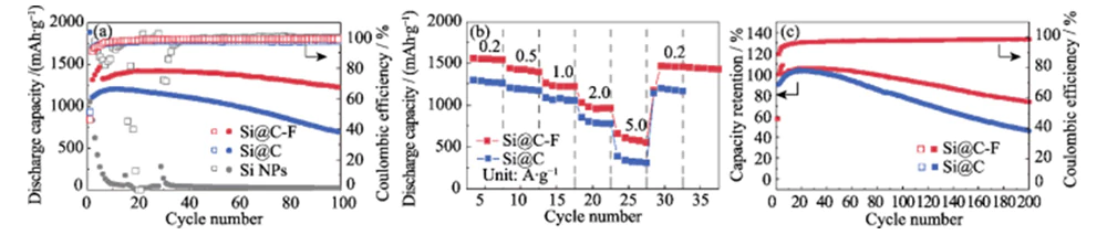
Fig. 5 (a) Cycling stability at a current density of 0.4 A·g-1 with anodes activated by 4 cycles at 0.2 A·g-1 before cycling, and (b) rate capability at various current densities ranging from 0.2 to 5.0 A·g−1 and (c) capacity retention at a current density of 0.2 A·g-1 for lithium storage in Si@C and Si@C-F anode
Table 1 Comparison of Si@C-F anode with reported Si-based anode in electrochemical performance
|
Materials |
Initial CE |
Initial capacity/(mAh·g-1) |
Capacity retention |
Ref. |
|
Si@C-F |
65.9% |
2640 |
85% (100 cycles) |
This work |
|
nano-Si/TiN@ |
71% |
2716 |
59.4% (110 cycles) |
[20] |
|
Si@C@RGO |
74.5% |
1474 |
48.9% (40 cycles) |
[21] |
|
Si@FA |
65% |
1334 |
68.7% (100 cycles) |
[22] |
|
p-Si@C |
58% |
3460 |
57.5% (100 cycles) |
[23] |
|
Si@void@C |
- |
900 |
70% (100 cycles) |
[24] |
|
Si/C@C |
- |
1120 |
80% (100 cycles) |
[25] |
At a high current density of 5.0 A·g-1, its capacity retention rate is approximately 78% higher than that of Si@C. When the current density is further reduced to 0.2 A·g-1, the specific capacity can be restored to 1450 mAh·g-1, indicating that its structure is highly stable during high-rate lithium storage. After 200 charge-discharge cycles at a current density of 0.2 A·g-1, the Si@C-F anode can maintain a specific capacity of >75%. The capacity retention rate of the Si@C anode without fluorination treatment is only 40% (Figure 5(c)). This anode also shows better lithium storage performance than the silicon anode material reported in the literature (Table 1). The fluorine doping amount in the coating carbon layer has a significant impact on the lithium storage performance of the Si@C-F anode. When the fluorine doping amount is below 1.8% atomic fraction, the cycling stability of the Si@C-F anode significantly improves as the fluorine doping amount increases (Figure 6). This is due to the enhanced effect of fluorine doping on the lithium ion transport properties of the carbon coating layer and the stability of the SEI film on the surface of the silicon material. When the fluorine doping ratio is too high (>2.7%), the carbon-coated Si anode material still maintains good cycle stability, but the specific capacity drops significantly. This is due to the loss of active Si caused by gas-phase fluorine species etching during high-temperature fluorination. When the fluorine doping amount is 1.8 atomic percent, the Si@C-F anode exhibits optimal cycle stability and high specific capacity.
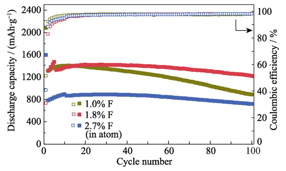
Fig. 6 Cycling stability of Si@C-F anodes with different F ratios at a current density of 0.4 A·g-1 with anodes activated by 4-10 cycles at 0.2 A·g-1 before cycling
The EIS spectra of Si@C and Si@C-F anodes consist of semi-arc curves in the mid- to high-frequency region and inclined straight lines in the low-frequency region (Figure 7(a)). The semi-arc curve in the mid- to high-frequency range is related to the charge transfer resistance (Rct), and the inclined straight line in the low-frequency range mainly reflects the Warburg impedance (ZW) of lithium ion diffusion [26]. Before charging and discharging, the Rct of Si@C-F and Si@C negative electrodes are similar, but the former has a lower ZW due to the highly defective fluorine-doped carbon layer covering the surface. After charge and discharge cycles, the Rct (5.51 Ω) of the Si@C-F anode is significantly lower than that of the Si@C anode (21.97 Ω) (Figure 7(b)), and the ZW is much lower than the latter. This shows that the fluorine-rich SEI interface film induced by the fluorine-doped carbon layer can effectively improve the interface charge and lithium ion transport capabilities.
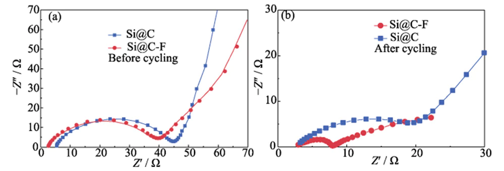
Fig. 7 Nyquist plots of the Si@C and Si@C-F anodes (a) before and (b) after cycling at a current density of 0.4 A·g-1
2.3 Characterization of electrode structure after charge and discharge
SEM characterization after charge and discharge cycles (Figure 8(a~c)) shows that due to the significant volume expansion effect of silicon during the lithium insertion process, the thickness of the Si@C electrode increased by 132.3%. This not only hinders the transmission of ions and electrons, increases the internal resistance and polarization of the electrode, but also causes huge mechanical stress, causing the electrode to rupture and separate from the current collector, causing the performance of the Si@C anode to rapidly decay (Figure 5(c)). In comparison, the electrode thickness of the Si@C-F anode increased by only 26.6% after charge and discharge cycles, and maintained good electrode structural stability (Figure 8(d~f)). This shows that the introduced fluorine-doped carbon layer can effectively buffer the volume expansion effect of lithium insertion in silicon materials at the micro scale, thereby enhancing the structural stability of the electrode at the macro scale from the bottom up.
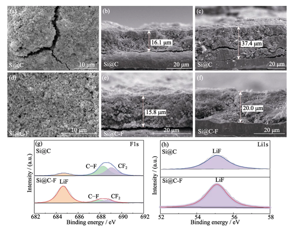
Fig. 8 Top SEM images of (a) Si@C and (d) Si@C-F anodes after cycling; Cross-section SEM images of (b, c) Si@C and (e, f) Si@C-F anodes (b, e) before and (c, f) after cycling; High-resolution (g) F1s and (h) Li1s XPS spectra of SEI on Si@C and Si@C-F anodes after cycling
The composition of the SEI film on the surface of Si@C and Si@C-F negative electrodes after charge and discharge cycles was analyzed by XPS (Figure 8(g~h)). In the high-resolution F1s XPS spectrum, the binding energy peaks at the binding energies of 684.8, 688.3, and 689.1 eV correspond to LiF, C-F bonds, and CF2, respectively. Correspondingly, there are also characteristic peaks corresponding to LiF species in the high-resolution Li1s XPS spectrum, indicating that an SEI film containing LiF species is formed on the surface of the silicon anode. Compared with the Si@C anode, the LiF content on the surface of the Si@C-F anode is higher, indicating that the LiF in the SEI film comes not only from the decomposition of lithium salts in the electrolyte, but also from the F in the fluorine-doped carbon layer. The formation of high-modulus LiF can effectively increase the structural strength of the SEI film and inhibit the volume change of lithium insertion in silicon materials. At the same time, the wide bandgap and insulating properties of LiF can reduce the SEI thickness and reduce the initial irreversible lithium loss. LixSi alloy, the lithiation product of LiF and Si, has a high interfacial energy and can better adapt to the plastic deformation of the lithiated silicon anode during cycling, thereby further improving the cycling stability of the electrode [19].
3 Conclusion
In this study, fluorine-doped carbon-coated nano-silicon materials were prepared through a simple and low-toxic gas-phase fluorination method. Research shows that fluorine doping (1.8% F), on the one hand, increases the defects of the carbon coating layer on the silicon surface, and provides abundant lithium ion transport channels while tightly coating nano-silicon to suppress its volume expansion. On the other hand, a highly stable SEI film rich in LiF is induced on the surface of the nano-silicon material, further improving the stability and Coulombic efficiency of the silicon anode. Thanks to this, the first Coulombic efficiency of the fluorine-doped carbon-coated nano-silicon anode improved to 65.9%. At a current density of 0.2~5.0 A·g-1, it exhibits a high specific capacity of 1540~580 mAh·g-1, and can maintain >75% of the initial capacity after 200 cycles. This work provides new ideas for the design and construction of silicon anode materials with high capacity and high stability.
Reference
[1] NIU S S, WANG Z Y, YU M L, et al.MXene-based electrode with enhanced pseudocapacitance and volumetric capacity for power- type and ultra-long life lithium storage.ACS Nano, 2018, 12(4): 3928.
[2] SU X, WU Q L, LI J C, et al.Silicon-based nanomaterials for lithium-ion batteries: a review.Advanced Energy Materials, 2014, 4(1): 1300882.
[3] GE M Z, CAO C Y, GILL M B, et al.Recent advances in silicon- based electrodes: from fundamental research toward practical applications.Advanced Materials, 2021, 33(16): 2004577.
[4] LI P, ZHAO G Q, ZHENG X B, et al.Recent progress on silicon- based anode materials for practical lithium-ion battery applications.Energy Storage Materials, 2018, 15: 422.
[5] LIU X H, ZHONG L, HUANG S, et al.Size-dependent fracture of silicon nanoparticles during lithiation.ACS Nano, 2012, 6(2): 1522.
[6] LUO W, WANG Y X, CHOU S L, et al.Critical thickness of phenolic resin-based carbon interfacial layer for improving long cycling stability of silicon nanoparticle anodes.Nano Energy, 2016, 27: 255.
[7] DOU F, SHI L Y, CHEN G R,Silicon/carbon composite anode materials for lithium-ion batteries.Electrochemical Energy Reviews, 2019, 2(1): 149.
[8] JIA H P, ZOU L F, GAO P Y, et al.High-performance silicon anodes enabled by nonflammable localized high-concentration electrolytes.Advanced Energy Materials, 2019, 9(31): 1900784.
[9] CHOI S H, KWON T W, COSKUN A, et al.Highly elastic binders integrating polyrotaxanes for silicon microparticle anodes in lithium ion batteries.Science, 2017, 357: 279.
[10] LI Z H, ZHANG Y P, LIU T F, et al.Silicon anode with high initial Coulombic efficiency by modulated trifunctional binder for high‐areal-capacity lithium-ion batteries.Advanced Energy Materials, 2020, 10(20): 1903110.
[11] XU Z L, CAO K, ABOUALI S, et al.Study of lithiation mechanisms of high performance carbon-coated Si anodes by in-situ microscopy.Energy Storage Materials, 2016, 3: 45.
[12] TEKI R, MONI K D, RAHUL K, et al.Nanostructured silicon anodes for lithium ion rechargeable batteries.Small, 2009, 5(20): 2236.
[13] XIA S X, ZHANG X, LUO L L, et al.Highly stable and ultrahigh- rate Li metal anode enabled by fluorinated carbon fibers.Small, 2021, 17: 2006002.
[14] ZHANG S L, WANG X, HO K S, et al.Raman spectra in a broad frequency region of p-type porous silicon.Journal of Applied Physics, 1994, 76(5): 3016.
[15] HUANG W, WANG Y, LUO G H, et al.99.9% Purity multi-walled carbon nanotubes by vacuum high-temperature annealing .Carbon, 2003, 41(13): 2585.
[16] MCDOWELL M T, LEE S W, NIX W D, et al.25th Anniversary article: understanding the lithiation of silicon and other alloying anodes for lithium-ion batteries.Advanced Materials, 2013, 25(36): 4966.
[17] KEY B, MORCRETTE M, TARASCON J M.Pair distribution function analysis and solid state NMR studies of silicon electrodes for lithium ion batteries: understanding the (de)lithiation mechanisms .Journal of American Chemical Society, 2011, 133(3): 503.
[18] GAO H, XIAO L S, PLUMEL I, et al.Parasitic reactions in nanosized silicon anodes for lithium-ion batteries.Nano Letters, 2017, 17(3): 1512.
[19] CHEN J, FAN X L, LI Q, et al.Electrolyte design for LiF-rich solid-electrolyte interfaces to enable high-performance microsized alloy anodes for batteries.Nature Energy, 2020, 5(5): 386.
[20] ZHANG P, GAO Y Q, RU Q, et al.Scalable preparation of porous nano-silicon/TiN@carbon anode for lithiumion batteries.Applied Surface Science, 2019, 498: 143829.
[21] SU M R, WAN H F, LIU Y J, et al.Multi-layered carbon coated Si-based composite as anode for lithium-ion batteries.Powder Technology, 2018, 323: 294.
[22] PU J B, QIN J, WANG Y Z, et al.Synthesis of micro-nano sphere structure silicon-carbon composite as anode material for lithium- ion batteries.Chemical Physics Letters, 2022, 806: 140006.
[23] GAO R S, TANG J, YU X L, et al.A sandwich-like silicon-carbon composite prepared by surface-polymerization for rapid lithium-ion storage.
Nano Energy, 2020, 70: 104444.
[24] GONG X H, ZHENG Y B, ZHENG J, et al.Yolk-shell silicon/ carbon composites prepared from aluminum-silicon alloy as anode materials for lithium-ion batteries.Ionics, 2021, 27: 1939.
[25] LIA Y R, WANG R Y, ZHANG J W, et al.Sandwich structure of carbon-coated silicon/carbon nanofiber anodes for lithium-ion batteries.Ceramics International, 2019, 45: 16195.
[26] YANG X M AND ROGACH A L.Electrochemical techniques in battery research: a tutorial for nonelectrochemists.Advanced Energy Materials, 2019, 9(25): 1900747.