Chinese
 français
 Deutsch
 italiano
 español
 português
 Nederlands
 日本語
日本語 한국의
한국의




Categories
new blog
- Conductive Materials for Lithium Batteries: CNT vs Graphene Guide
- Step-by-Step Guide to Partnering with a Sodium-Ion Battery Technology Developer in China
- A Complete Guide to Implementing Industrial Solid State Battery Technology in Manufacturing
- How to Select a Professional Battery Equipment Provider for High-Volume Production
- Guide to Procuring High-Quality Lithium Battery Coating Machines from Chinese Manufacturers
Tags
Conductive Materials for Lithium Batteries: CNT vs Graphene Guide
Conductive Materials in Lithium-Ion Batteries: Carbon Nanotubes, Graphene, and Beyond
Active material determines how much energy a cell can store. The conductive additive determines whether that energy can be extracted.
This distinction is underestimated in most electrode formulations. A cathode with 96% NMC and 2% carbon black looks efficient on paper—maximum active material, minimum dead weight. In practice, that formulation may deliver 15% less usable capacity than a 94% NMC formulation with a properly engineered conductive network.
The conductive additive is the electronic highway system of the electrode. When it is underspecified, over-dispersed, or poorly distributed, the active material becomes electrochemically isolated. Lithium ions can move. Electrons cannot.
This guide compares the four dominant conductive material classes—carbon black, carbon nanotubes, graphene, and conductive graphite—against measurable procurement criteria: loading requirements, percolation behavior, dispersion difficulty, and equipment cost.
The Conductive Additive Comparison Matrix
| Material | Typical Loading (wt%) | Specific Surface Area (m²/g) | Aspect Ratio | Electrical Conductivity (S/cm) | Relative Cost Index |
| Carbon black (Super P) | 2–5 | 60–70 | ~1 (spherical) | 10–100 | 1.0x |
| Acetylene black | 2–4 | 60–80 | ~1 | 50–200 | 1.2x |
| Ketjenblack (EC-300J) | 1–3 | 800–1,400 | ~1 | 100–500 | 4–6x |
| MWCNT | 0.5–2 | 200–400 | 100–1,000 | 10³–10⁴ | 8–15x |
| SWCNT | 0.1–0.5 | 500–1,200 | 1,000–10,000 | 10⁴–10⁵ | 40–80x |
| Graphene nanoplatelets | 1–3 | 500–1,500 | 100–1,000 (2D) | 10³–10⁴ | 10–20x |
| Conductive graphite | 3–8 | 10–30 | ~1 | 10²–10³ | 0.8x |
The cost index is not the decision metric. The decision metric is cost per unit of electrode conductivity achieved—and that figure depends almost entirely on dispersion quality.
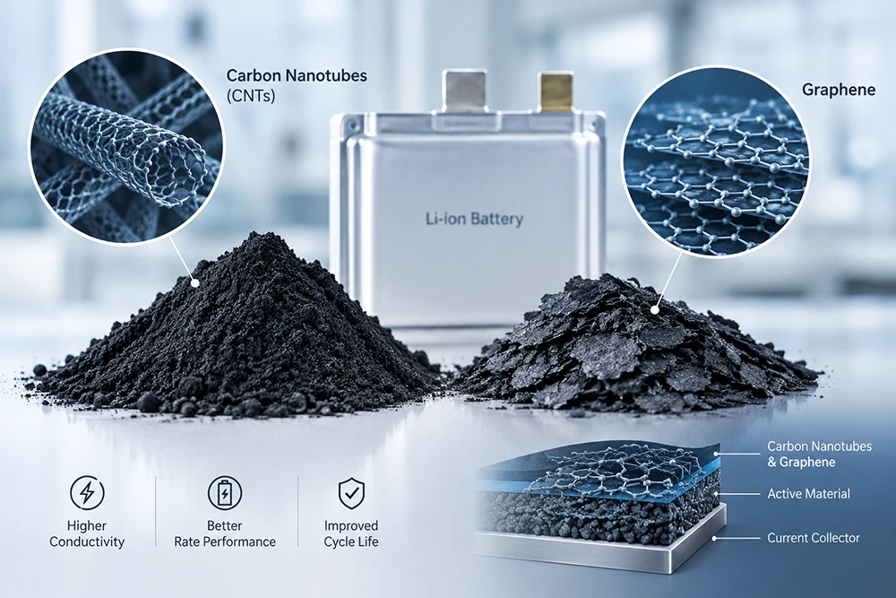
Carbon Black: The Industry Baseline and Its Limits
Carbon black remains the default conductive additive for over 90% of lithium-ion production. It is inexpensive, well-understood, and compatible with essentially every cathode chemistry.
The mechanism is point-to-point contact. Carbon black particles form chains and clusters that bridge active material particles. At 2–3 wt% loading, sufficient contacts exist to establish a continuous electronic path—the percolation threshold.
The limitation: Point-contact networks are fragile. During calendering, carbon black chains are compressed and broken. After calendering to 3.2 g/cm³, a Super P network can lose 30–40% of its original conductivity. The cell still cycles, but rate capability and high-current performance degrade.
Where carbon black stops working:
- High-nickel NMC (Ni > 80%) with low electronic conductivity at the particle surface
- Silicon-dominant anodes, where volume expansion disrupts the carbon network on every cycle
- Thick electrodes (>4 mAh/cm² areal loading), where the electron path length exceeds the point-contact network's reach
- Solid-state cathodes, where the electrolyte provides no ionic bridging and the electronic network must be self-supporting
Carbon Nanotubes: Percolation at Fractional Loading
CNTs change the percolation equation. A single multi-walled nanotube with an aspect ratio of 500 provides the same electronic connectivity as several hundred carbon black particles—at a fraction of the mass.
The dosage shift is substantial:
| Conductive System | Loading Required for Equivalent Conductivity | Impact on Energy Density (vs. 3wt% carbon black) |
| Carbon black only | 3.0 wt% | Baseline |
| Carbon black + 0.5 wt% MWCNT | 2.0 wt% total | +0.5% active material |
| MWCNT only | 1.0 wt% | +1.5% active material |
| MWCNT + 0.1 wt% SWCNT | 0.5 wt% total | +2.2% active material |
At cell level, 2% additional active material translates to roughly 2% higher energy density—a meaningful gain for EV and energy storage programs where every Wh/kg is contested.
The Dispersion Problem That Kills CNT Adoption
CNTs arrive as entangled bundles held together by van der Waals forces. Those bundles must be separated into individual tubes to deliver their aspect-ratio advantage.
If dispersion fails, three outcomes occur:
- Agglomerates act as defects. Undispersed CNT bundles behave as conductive particles, not networks. Conductivity improvement is marginal. Cost is fully incurred.
- Localized over-concentration. Agglomerates create regions of high conductivity adjacent to regions of none. Current density becomes non-uniform during charging. Localized lithium plating follows.
- Mechanical failure in coating. Large CNT bundles plug slot die filters and create die lines across the electrode surface.
Documented failure case: A production line substituted 0.8 wt% MWCNT for 2 wt% carbon black without upgrading the mixing process. Coating produced visible die lines at 15 mm intervals across the web. Electrode resistance measured 40% higher than the carbon black baseline. The root cause was CNT agglomerates exceeding 50 μm in diameter passing through the slot die gap and disrupting the flow field.
Engineering Insight: CNT dispersion is a shear-energy problem, not a time problem. Extending mixing time at low shear does not separate bundles—it circulates them. Achieving individual tube separation requires either high-shear rotor-stator dispersion, three-roll milling, or a pre-dispersed CNT paste with a verified dispersion quality metric. TOB New Energy supplies high-shear dispersion and mixing equipment for CNT conductive slurry with validated dispersion quality testing (particle size D50 < 5 μm, D99 < 20 μm) to prevent agglomerate-driven coating defects.
Graphene: The Restacking Problem Nobody Budgets For
Graphene nanoplatelets offer high surface area and in-plane conductivity that exceeds CNTs in theory. The 2D geometry provides broad contact with active material particles rather than the point or line contact of carbon black and CNT.
The manufacturing reality differs from the datasheet.
Graphene nanoplatelets have a strong tendency to restack into graphite-like structures during drying. As solvent evaporates, capillary forces pull adjacent platelets together. The result is a conductive additive that arrives as high-performance graphene and ends up as low-performance graphite in the finished electrode.
Mitigation strategies and their trade-offs:
| Strategy | Effectiveness | Cost Impact |
| Surface functionalization (carboxyl, hydroxyl groups) | Moderate; reduces restacking but lowers in-plane conductivity | +30–60% material cost |
| Hybrid system: graphene + CNT | High; CNTs act as spacers between platelets | +10–20% total conductive additive cost |
| Rapid drying profile | Moderate; limits restacking window | Constrains drying oven design |
| Electrolyte additive for in-situ separation | Under development | Unproven at production scale |
For most electrode formulations, graphene delivers best results in a hybrid architecture with CNTs, not as a standalone conductive additive.
Conductive Graphite: The Underrated Option for Anodes
Conductive graphite is rarely discussed in cathode formulations, but it plays a specific and valuable role in anode engineering.
Natural or synthetic graphite with 10–30 m²/g surface area is added at 3–8 wt% to anode formulations, particularly for:
- Silicon-blended anodes, where graphite improves electronic contact between silicon particles and accommodates some volume expansion
- Fast-charge anodes, where the conductive path must support high current densities without excessive polarization
- LFP anodes in some configurations
Conductive graphite is inexpensive and disperses far more easily than CNT or graphene. Its limitation is mass loading—3–8 wt% is dead weight that reduces energy density. This constrains it to applications where rate capability and cycle life outweigh gravimetric energy density.
Troubleshooting Guide: Conductive Network Defects
| Symptom | Likely Root Cause | Diagnostic Method | Corrective Action |
| High electrode resistance (>50 Ω·cm after calendering) | Insufficient conductive loading or broken network | Four-point probe measurement across electrode | Increase loading 0.5 wt% or switch to high-structure carbon black |
| Capacity fade at >1C rate | Point-contact network failure at high current | Rate capability test; dQ/dV analysis | Replace 50% of carbon black with MWCNT at 0.5–1 wt% |
| Die lines in coating | Undispersed CNT or graphene agglomerates | Filtration test; grindometer on slurry | Upgrade to high-shear dispersion; verify D99 < 20 μm |
| Non-uniform electrode resistance across web | Poor dispersion uniformity | Resistance mapping at 5 positions across width | Increase mixing energy; validate with particle size distribution |
| Electrode cracking after drying | Excessive conductive additive surface area | Visual inspection; adhesion peel test | Reduce Ketjenblack or graphene loading; increase binder by 0.3 wt% |
| Low first-cycle efficiency | Conductive additive consuming lithium | Formation dQ/dV; ICP analysis of cycled cell | Reduce high-surface-area carbon content |
Equipment Implications: Dispersion Is the Bottleneck
Conductive material selection determines formulation cost. Dispersion equipment determines whether that cost is realized or wasted.
Equipment requirements by conductive material type:
| Conductive Material | Mixing Method | Key Equipment Specification |
| Carbon black | Standard planetary vacuum mixing | Vacuum to -0.09 MPa; shear rate 1,000–5,000 s⁻¹ |
| MWCNT (powder) | High-shear dispersion + planetary mixing | Rotor tip speed >20 m/s; dispersion time 30–90 min |
| MWCNT (pre-dispersed paste) | Planetary vacuum mixing only | Paste solid content 5–10%; verified D99 < 20 μm |
| Graphene nanoplatelets | High-shear dispersion + controlled drying | Platelet size D50 5–15 μm; drying ramp rate <5°C/min |
| Hybrid CNT/graphene | Sequential addition: CNT first, graphene second | Two-stage dispersion with intermediate particle size check |
The equipment cost difference between a standard mixing room and a CNT-capable mixing room is significant. A high-shear disperser with the required tip speed and vacuum capability adds $80,000–200,000 to a production line. A pre-dispersed CNT paste eliminates that capital cost but adds $15–40 per kilogram to material cost.
Frequently Asked Questions (FAQ)
Q: What is the minimum CNT loading required to replace carbon black?
A: 0.5–1.0 wt% MWCNT can replace 2–3 wt% carbon black while maintaining equivalent electrode conductivity, provided dispersion achieves individual tube separation (D99 < 20 μm). Below 0.5 wt%, the percolation network becomes unreliable.
Q: Can graphene completely replace carbon black as a conductive additive?
A: Not recommended. Graphene restacking during drying reduces its effective conductivity, and standalone graphene formulations typically show higher electrode resistance than hybrid graphene/CNT systems. Graphene performs best at 1–2 wt% combined with 0.3–0.5 wt% CNT.
Q: How do I verify that my CNT dispersion is adequate before coating?
A: Three metrics: particle size distribution (D50 < 5 μm, D99 < 20 μm), filtration test through a 25 μm filter with <1% residue, and slurry resistivity measurement. If all three pass, coating defects from agglomerates are unlikely.
Q: Are conductive additives necessary for solid-state battery cathodes?
A: Yes, and at higher loadings than liquid-electrolyte cells. Solid electrolytes provide no electronic conduction pathway, so the conductive network must be fully self-supporting. Typical solid-state cathode formulations use 3–5 wt% conductive carbon combined with 20–40 wt% solid electrolyte.
Ready to Engineer Your Conductive Network?
Conductive additive selection is a formulation decision. Conductive network performance is an equipment decision. The best CNT in the world delivers no benefit if it arrives at the coating die as an agglomerate.
TOB New Energy supplies complete conductive material handling and dispersion systems—from high-shear dispersers and vacuum planetary mixers to pre-dispersed CNT paste sourcing and electrode coating lines. Equipment is manufactured and validated at a single source factory in Xiamen, China, with dispersion quality testing performed on your actual cathode chemistry before shipment. Request a conductive material and dispersion equipment consultation with factory-direct pricing.
 subscribe to us