
- Home
- >
Other Equipment
- >
Vacuum Magnetron Sputtering Coating Machine
Categories
Hot Products
Loading...
Vacuum Magnetron Sputtering Coating Machine
Brand:
TOB NEW ENERGYitem no.:
TOB-1100X-SPC-16Morder(moq):
1Payment:
L/C,T/Tproduct origin:
Chinashipping port:
XIAMEN
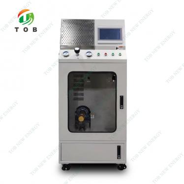
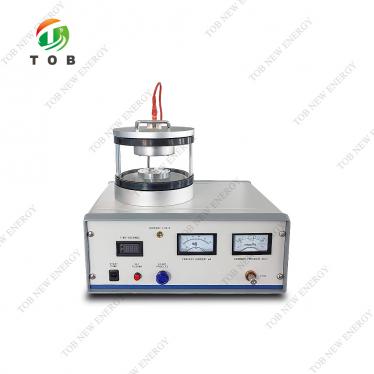
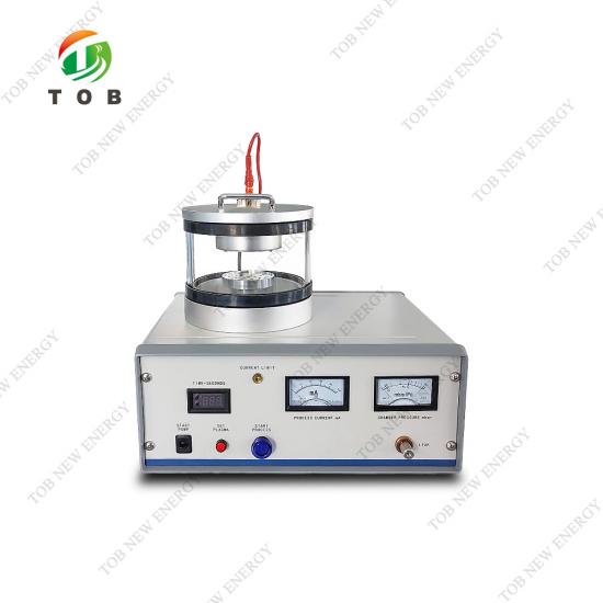
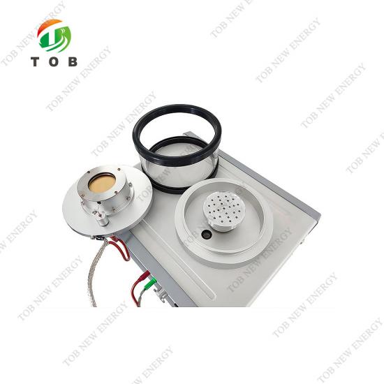
TOB-1100X-SPC-16M Magnetron Sputter Coater for Battery R&D and SEM Sample Preparation
1. Product Overview and Ideal Applications
A magnetron sputter coating machine is a physical vapor deposition (PVD) tool that uses magnetically confined plasma to eject target atoms and deposit a thin, uniform conductive layer on a substrate. The TOB-1100X-SPC-16M is a benchtop‑designed laboratory coater purpose‑built for battery material research and routine SEM sample preparation.
In everyday battery work, you use it to coat NMC, LFP, graphite, silicon, or solid‑electrolyte samples with gold, silver, or copper so the SEM can clearly image surface details without charging artefacts. It can also be used for electrode surface treatments, like modifying interfacial contact, when you’re prototyping coin cells or small pouch cells.
What makes this machine different from generic low‑cost sputterers isn’t a longer feature list—it’s the engineering details that matter in a real battery lab: the Ø50 mm target and Ø160 mm chamber ensure uniform coverage across multiple samples; the ceramic‑sealed high‑voltage electrode removes a common vacuum leak point; and the built‑in Peltier cooling (with optional water‑cooled stage) protects heat‑sensitive separators and solid electrolytes that would certainly deform under an un‑cooled head.
With 24 years in battery equipment, TOB’s engineers have repeatedly seen how poor sample prep can derail an entire materials study—this coater is our direct response to that pain point.
Ideal for:
- University battery materials labs requiring consistent, publication‑quality SEM images
- Pilot‑line QA teams that need reproducible coating thickness across multiple samples every single day
- Research groups working with moisture‑sensitive sulfide or oxide solid‑state electrolytes
- Any lab tired of fighting unstable plasma and short‑lived rubber seals on entry‑level sputterers

⚙️ Not sure which target material or parameter to start with? Contact our lab equipment engineers directly—include your sample type and we’ll suggest a starting recipe.
2. Where This Coater Fits in Battery R&D: Applications and Process Best Practices
Applicability
The TOB-1100X-SPC-16M handles sample arrays up to about 100 mm across, making it suitable for electrode discs, sheet electrodes, separator films, and small pouch cell components. It supports all common battery chemistries: lithium‑ion (NMC, LFP, LCO, graphite, silicon), sodium‑ion (hard carbon, Prussian‑blue analogues), solid‑state (oxide, sulfide electrolytes), and supercapacitors. Because sputtering doesn’t require substrate heating, even polymeric separators or composite electrolytes with organic binders can be coated without thermal damage—an important advantage when your sample absolutely cannot tolerate extra heat.
Positioning in the Battery R&D Workflow
This coater sits in the materials characterization stage, right after electrode/electrolyte synthesis and before SEM, EDS, or other high‑vacuum surface‑analysis techniques. A typical morning in the lab: you synthesise a new cathode powder, make a slurry‑coated electrode, punch a small disc, and then use the TOB-1100X-SPC-16M to apply a ~8 nm gold layer before loading it into the SEM. The whole coating step takes about 90 seconds.
Process Optimisation Best Practices (from real application experience)
Pump‑down moisture: If your electrode samples still contain trace NMP or moisture from slurry processing, they’ll outgas during pump‑down and make the plasma unstable. Extend the initial pump‑down time by an extra 30‑60 seconds. The relatively large Ø160 mm chamber gives these volatiles room to expand, helping stabilise the plasma faster than a tiny chamber would.
- Target distance: For irregular sample shapes, adjust the sample shelf so the top surface is roughly 40–60 mm from the target. Too close and you risk local overheating; too far and the coating uniformity drops off.
- Current and pressure tuning: For gold coatings on battery particles, 30–40 mA with an argon pressure around 0.05 mbar usually gives a fine‑grained film. Crank the current much higher only if you need a thicker layer quickly—but watch the substrate temperature.
- Target cleaning: Between different target materials, wipe the glass jar and the O‑ring groove with isopropyl alcohol. Even a tiny amount of cross‑contamination can show up in EDS spectra later.How the Sputter Coater Operates in Real Lab Conditions
3. How the Sputter Coater Operates in Real Lab Conditions
Here’s what actually happens when you run the TOB-1100X-SPC-16M, step by step.
After you place your samples on the stage and close the glass bell jar, the rotary vane pump (2 L/s) pulls the chamber down to a base pressure of ≤4×10⁻² mbar. In battery labs, this pump‑down stage is where many sputterers struggle: residual solvent or moisture from electrode coatings evolves into vapour, raising the background pressure just enough to make plasma ignition erratic. The larger chamber volume gives these volatiles a bigger space to distribute, and the fine‑control micro‑vacuum valve lets you quickly flush the system with argon to aid pump‑down stability.
Once the target vacuum is reached, you introduce high‑purity argon (≥99.99%) through the micro‑valve. You then apply DC voltage—up to 1600 V—to the Ø50 mm target. The strong permanent magnets behind the target create a closed magnetic trap right above the target surface. Why does this matter in daily use? It traps energetic electrons near the target, boosting the ionisation of argon atoms and increasing the sputtering rate without needing higher voltage. This is why you can get a 10 nm gold layer in about 80 seconds at 40 mA, while still keeping substrate heating low enough for polymeric samples.
The control logic is straightforward but essential for repeatability. You adjust the sputtering current via a dedicated controller (max 50 mA, optionally 100 mA) while watching the current meter and vacuum gauge. By balancing argon flow and pressure, you stabilise the plasma at your chosen current. Then you set the digital timer (up to 9999 s) to cut off the high‑voltage automatically. This means that whether your lab has a dedicated technician or you’re training a new graduate student, the same settings produce the same thickness—fundamental for reproducible SEM comparisons.
Cooling is another crucial point that you feel rather than see in a brochure. The sputter head uses a built‑in Peltier cooler as standard. For battery separators and solid electrolytes, even modest heating can cause shrinkage or phase changes. When you expect that risk, the optional water‑cooled carrier table pulls heat away from the substrate, keeping it close to ambient. In practice, this combination means you can coat a polyethylene separator for an ageing test and still see the original pore structure in the SEM afterward—something we’ve seen fail many times on uncooled diode coaters.
4. Key Engineering Advantages for Battery Researchers
- Oversized Ø50 mm Target for Practical Uniformity
Some compact sputterers use a Ø30 mm target, which forces you to place samples very close to the centre to get a consistent coating. The TOB’s Ø50 mm target and Ø160 mm chamber deliver a thickness variation under ±5 % across an ~80 mm circle. In plain terms: you can load multiple electrode discs at once and trust they’ll all look equally well‑prepared in the SEM.
- Ceramic‑Sealed High‑Voltage Electrode
This is one of those details that separates a sputterer you can rely on for years from one that starts leaking after 12 months. In busy labs where the coater runs several times a day, rubber O‑rings around the high‑voltage feedthrough can harden and crack due to plasma UV and temperature cycling. The ceramic seal on the TOB-1100X-SPC-16M simply sidesteps that ageing mechanism, reducing maintenance interruptions.
- Active Cooling That Protects Sensitive Battery Materials
Standard Peltier cooling on the sputter head means you don’t need an external water connection for routine coating of cathode powders. But when you move to thin separators, sulfide‑based solid electrolytes, or polymer‑gel interfaces, you can engage the optional water‑cooled carrier table. The two‑stage cooling ensures your sample stays below its critical temperature during the entire pump‑down and sputtering cycle—a feature we specifically developed after seeing too many deformed separator samples from researchers using basic dc coaters.
- Precise Current and Gas Flow Control
The continuous‑adjustment sputtering current controller and the micro‑vacuum valve with Ø3 mm hose connection allow you to fine‑tune the deposition exactly to your material’s requirements. This isn’t just about “accuracy”; it’s about the freedom to develop a dedicated SOP for each battery chemistry your lab works on. When a new PhD student needs to coat a novel solid‑electrolyte pellet, the incremental controls make it far easier to find a stable processing window.
- Auto‑Cut‑Off Timer for Reproducible Work
The digital timer (9999 s max.) automatically switches off the high‑voltage when the set time is reached. This removes operator‑to‑operator variability—the kind that can turn a well‑calibrated process into an inconsistent one. Combined with real‑time vacuum and current monitoring, you can catch any anomaly (pressure spike, current drop) immediately and stop the run before the sample is damaged.
5. Complete Technical Specifications
|
Product Name |
|
|
Product Model |
TOB-1100X-SPC-16M |
|
Installation Condition |
This equipment is required to be used at an altitude of 1000m or less, at a temperature of 25℃±15℃and a humidity of 55%Rh±10%Rh. 1. water: the equipment needs to be equipped with optional self-circulating cooling water machine (filling pure water or deionized water) 2. electricity: AC220V 50Hz, must have a good grounding 3. gas: equipment chamber to be filled with argon (purity 99.99% or more), need to provide their own argon gas cylinder (with pressure reducing valve) 4. Working table: size 600mm×600mm×700mm, load-bearing 50kg or more. 5. Ventilation device: not required |
|
Major Parameter |
1. Target: Ø50mm |
|
2. Vacuum chamber: Ø160mm×120mm |
|
|
3. vacuum degree:≤4×10⁻²mbar |
|
|
4, max current: 50mA (optional 100mA) |
|
|
5. Limit time can be set: 9999s |
|
|
6. Micro vacuum valve: Connect Ø3mm hose |
|
|
7. limit voltage: 1600V DC |
|
|
8. mechanical pump: 2L/s |
|
|
9. Target material: Size requirement:φ50mm×(0.1-0.5)mm(thickness) Suitable for sputtering Au, Ag, Cu and other metals (available in our company) |
|
|
10. Size: 360mm×300mm×380mm Overall weight: 50Kg, Net weight: 15Kg |
6. Common Coating Defects & Practical Troubleshooting
Battery materials are rarely inert, flat substrates. Porosity, surface roughness, and residual binders can all influence sputtering results. Here are the most frequent issues we see labs run into, and how to address them using the TOB-1100X-SPC-16M.
| Problem | Possible Cause | How TOB’s Coater Helps / Action to Take |
| Non‑uniform coating (thicker in the centre, thinner at edges) | Sample too close to the target or chamber pressure too high, shortening mean free path. | Adjust the stage height to maintain ≥45 mm distance. The large chamber and wide target naturally improve uniformity; ensure samples are within an 80 mm circle. |
| Plasma difficult to ignite or unstable | Residual moisture/solvent in the chamber from electrode samples; small chamber volume exacerbates this. | Extend pump‑down time. The Ø160 mm chamber gives volatiles room to expand, and the micro‑valve allows a gentle argon pre‑flush to stabilise pressure before ignition. |
| Separator film visibly shrinks or loses pore structure | Excessive heat from uncooled sputter head and prolonged exposure. | Eng age the water‑cooled carrier table (optional). Lower the sputtering current to 20–30 mA and keep coating time under 60 s. Post‑coating, wait 30 s in vacuum before venting. |
| Coating flaking off from the sample surface | Poor adhesion due to contamination, or excessively thick brittle films. | Clean the sample surface with a brief argon plasma pre‑treatment (run at 10 mA for 20 s without a shutter). Reduce final thickness—a 5–8 nm layer often adheres better than 15 nm+. |
| Excessive carbon or oxygen signal in EDS after coating | Chamber not properly cleaned, or pump oil backstreaming. | Regularly wipe the glass jar and O‑ring with isopropyl alcohol. Use the optional diffusion pump or a cold trap if ultra‑clean films are required; consult TOB for an upgrade path. |
This troubleshooting guide is built on feedback from hundreds of battery labs. If you encounter a problem not listed here, reach out to our application group—we often see issues that aren’t in the standard manuals.
7. Why Battery Labs Switch from Entry‑Level Coaters: TOB in Comparison
| Feature | TOB-1100X-SPC-16M | Typical Low‑Cost Lab Sputter Coater |
| Target size | Ø50 mm | Ø30–40 mm |
| Chamber size | Ø160 mm × 120 mm | Ø100–120 mm |
| High‑voltage seal | Ceramic‑sealed electrode (long‑life) | Rubber O‑ring seal (prone to ageing) |
| Sample cooling | Peltier‑cooled head; water‑cooled stage option | None (natural air convection only) |
| Sputtering current control | Continuous adjustment + dedicated meter | Step‑wise or fixed current only |
| Gas flow control | Micro‑vacuum valve with fine regulation (Ø3 mm connection) | Often a simple needle valve or no fine control |
| Timer | Digital, up to 9999 s with auto cutoff | Mechanical or no timer |
| Coating uniformity (over 80 mm area) | Thickness variation < ±5 % | Typically > ±15 % |
| Typical gold coating rate (at 40 mA) | Approx. 10 nm/min | Approx. 6 nm/min |
| Maintenance cycles | Yearly seal check recommended; robust design | Frequent O‑ring replacement required |
Why Battery Labs Upgrade from Entry‑Level Coaters
If your current sputterer is an un‑cooled diode coater, you’ve probably already experienced some version of this: after coating a PE separator, the SEM reveals a melted, feature‑less surface instead of the expected pore network. Or perhaps the plasma takes three tries to ignite because the chamber is just too small to handle electrode outgassing. The TOB-1100X-SPC-16M is engineered specifically to overcome these daily frictions, not by adding complicated features, but by getting the fundamentals right—larger chamber, active cooling, ceramic seals, and a magnetron head that stays stable at low pressure. This translates to fewer wasted batches and more time spent on actual materials analysis.
8. Engineering FAQ — Sputter Coating for Battery Samples
Q1: Can the TOB-1100X-SPC-16M sputter platinum or iridium for high‑resolution SEM of battery electrodes?
Yes. The coater uses standard planar targets (φ50 mm × 0.1–0.5 mm), so you can install a Pt or Ir target as long as it matches that format. Keep in mind that sputtering rates for these metals are lower; you’ll typically need to increase the current to the maximum 50 mA and lengthen the coating time. For temperature‑sensitive samples, we strongly recommend using the water‑cooled stage to offset the additional heat.
Q2: How do I avoid thermal damage to a thin polymer separator during coating?
PE and PP separators can start to soften around 120 °C, and shrinking of the pore structure is irreversible. The simplest approach is: (1) use the water‑cooled carrier table option; (2) set the sputtering current to 25–30 mA; (3) limit coating time to 45–60 s for a 5 nm gold layer. Also, let the sample sit in vacuum for about 30 s after sputtering before you vent—this gives residual heat a chance to dissipate into the stage.
Q3: What’s a reliable gold coating thickness for SEM imaging of lithium‑ion cathode powders?
For secondary electron imaging at 5–10 kV, we find that 5–10 nm Au works well for NMC, LFP, and LCO. Thinner than 5 nm can leave islands that don’t fully suppress charging; thicker than 15 nm can bury fine surface texture. With the TOB-1100X-SPC-16M, you can reliably hit 8 nm by using a gold target at 35 mA for 80 s—calibrated once with a quartz crystal microbalance or AFM.
Q4: Our lab works with air‑sensitive solid electrolytes. Can we integrate the coater into a glovebox?
The TOB-1100X-SPC-16M is a benchtop system not designed for full glovebox integration, but the glass bell jar can be removed and the sample stage is accessible. Many labs transfer samples from the glovebox in a sealed transfer vessel and quickly mount them before pump‑down. If you need a fully glovebox‑integrated sputterer, contact us—TOB offers customised vacuum equipment for such demanding requirements.
Ready to move beyond one‑size‑fits‑all sputtering recipes? Send us your sample type and target thickness goal. Our engineers will provide a tailored starting‑point process and the full specification sheet.
tob.amy@tobmachine.com | +86 181 2071 5609
Previous:
Laboratory Hammer Crusher for Sample PreparationNext:
Winding Cores Reels for Electrode Roll
If you are interested in our products and want to know more details,please leave a message here,we will reply you as soon as we can.