Chinese
 français
 Deutsch
 italiano
 español
 português
 Nederlands
 日本語
日本語 한국의
한국의




Categories
Hot Products
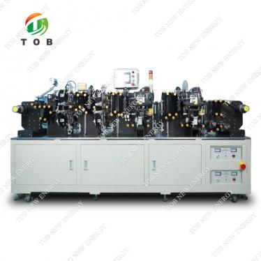
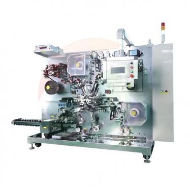
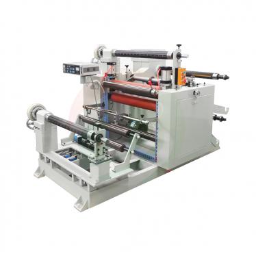
Patent CN215542414U - Non-Stop Roll Changeover Coating Machine
Oct 10,2026A lithium battery coating line whose feeding structure swaps in the next substrate web roll automatically - no stop, no splice, no operator at the unwind.
Full specification and drawings: CN215542414U on Google Patents
Electrode coating is the step that decides how much of a battery's designed capacity, safety and consistency ever reaches the finished cell - the specification calls good coating the basic premise of battery capacity, safety and consistency. But while the coating head itself improved, the machine around it had a blind spot: when a substrate web roll ran out, the line had to be stopped to load the next one. Continuous feeding was simply not possible.
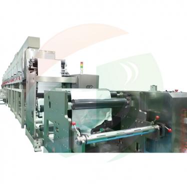
CN215542414U, filed on 1 September 2021, removes that stop. Its feeding structure queues fresh web rolls on a ramp, meters them one at a time into a storage trough with two hydraulically coupled gate plates, and detects the end of the running web with an infrared beam - so the spent core is pushed out and the next roll drops into place while the coater keeps coating.
Patent Information
| Publication number | CN215542414U |
| Application number | CN202122096805.9U |
| Title (original) | 一种带有连续上料装置的锂电池涂布机 (Coating Machine with Non-Stop Roll Changeover) |
| Inventors | Huang Zhengyao (Dany Huang); Chen Lucai (Tobey Chen) |
| Current assignee | XIAMEN TOB NEW ENERGY TECHNOLOGY Co., Ltd. - the registered entity of TOB NEW ENERGY |
| Filing date | 1 September 2021 |
| Grant date | 18 January 2022 |
| Document type | Utility model (granted, kind code U) |
| Legal status | Active |
| Anticipated expiration | 1 September 2031 |
| Drawings | 4 figures |
| Official record | CN215542414U on Google Patents |
The Production Problem This Patent Solves
The specification is blunt about the defect in the machines then available: the coating machine could not feed material continuously. A roll of substrate holds only so much web, and when it emptied, production stopped while an operator fitted a fresh roll. On a modern electrode line every such stop is idle time for the coating head, a fresh start-up transient for coating quality, and a reason the web's usable yield falls short of what the coating process should deliver.
How the Mechanism Works
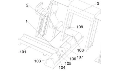
The machine is organised as three structures in line: a feeding structure (1), a coating structure (2) and a drying structure (3).
Queued rolls and the two gate plates
Fresh web rolls (107) wait on a small ramp (101) that leads to a storage trough (114). A first hydraulic gate plate (104) stands at the opening between ramp and trough; a second hydraulic gate plate (105) stands in the middle of the trough, where the roll that is actually in use rests on a support rod (106). An oil channel inside the trough connects the two plates hydraulically. When the running roll presses plate 105 down, the hydraulic coupling raises plate 104 and blocks the next roll from rolling off the ramp. A baffle (115) at the right end of the trough stops each new roll at the exact working position on the support rod.
The changeover cycle
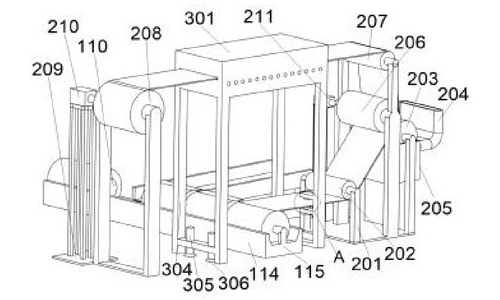
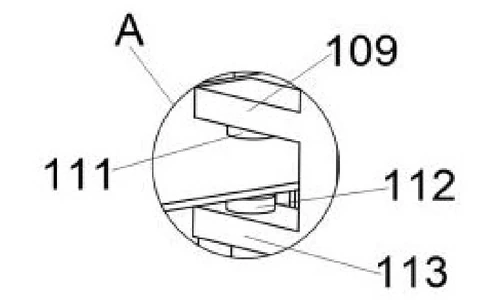
When the web (108) runs out, the web is no longer passing between the infrared emitter (111) and the infrared sensor (112) mounted on the drying-frame brackets. The sensor signals the controller of the hydraulic cylinder (103) at the left end of the trough. The cylinder extends its rod (110), pushing the spent core off the support rod, then retracts. With the trough momentarily empty, plate 105 is no longer pressed down, the hydraulic coupling lets plate 104 drop, and the next roll rolls into the trough and onto the support rod - pressing plate 105 again, which lifts plate 104 and re-arms the block. The changeover is complete without stopping the line.
Coating section
From the support rod, the web is guided by the first guide roller (202) into the coating structure (2). Slurry is fed through the inlet (204) into a raw material tank (205); a coating roller (203) above the tank picks up the slurry, and a squeeze roller (206) at the side of the coating roller metering the film. The coated web leaves over a second guide roller (207). A coating motor (211) on the first motor frame (201) drives the section.
Drying and rewind
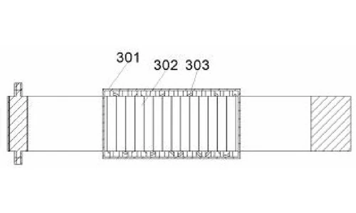
The web next enters the drying structure (3) on the left of the second guide roller. Inside the drying box (301), heating tubes (303) on the inner top wall and a heating roller (302) with an internal heater dry the coated layer; the heater and tubes are externally powered and controlled. After drying, the web travels to the wind-up roller (208) on the side of the drying structure, driven by a winding motor (210) under a second motor frame (209).
Claimed Benefits
| Benefit | Mechanism responsible |
|---|---|
| Continuous web feeding, no line stop at roll end | Ramp-and-trough feeder with two hydraulically coupled gate plates |
| Automatic changeover without operator judgement | Infrared emitter/sensor pair signalling the hydraulic cylinder |
| Reliable roll positioning | Baffle at the trough end locating each new roll on the support rod |
| Coating and drying in one pass | Coating roller/squeeze roller section by a heated drying box |
| Independent drives for coating and winding | Coating motor and winding motor on separate motor frames |
How It Compares with Stop-to-Splice Coating Feeding
The specification is blunt: coating machines available at the time could not feed material continuously. When a roll emptied, production stopped while an operator fitted a fresh roll - idle time for the whole line. This patent swaps the empty roll automatically while coating keeps running.
| Dimension | Conventional approach | This patent design |
|---|---|---|
| Roll change | Line stops while an operator fits a new roll | Ramp-and-trough feeder with two hydraulically coupled gate plates changes rolls without stopping |
| Trigger | Operator judgement and timing | Infrared emitter/sensor pair signals the hydraulic cylinder |
| Pass structure | Coating and drying handled apart from feeding | Coating and squeeze rollers by a heated drying box, coating and winding on independent drives |
Where This Technology Is Used Today
This patent covers the continuous-feeding architecture behind TOB's electrode coating machines. Keeping the web moving through roll changes is what lets our coaters hold a steady coating window across a full run of electrode foil.
Related equipment enquiries: request a quote
Frequently Asked Questions
What does patent CN215542414U cover?
It covers a lithium battery coating machine with a feeding structure that changes substrate web rolls automatically, together with a coating structure and a drying structure. Queued rolls are held back by a hydraulically coupled gate-plate pair, and an infrared web-end sensor triggers a hydraulic cylinder to release the next roll, so feeding is continuous.
Why is continuous web feeding important on a coating machine?
Coating quality is the basic premise of battery capacity, safety and consistency. If the line must be stopped whenever a web roll runs out, each restart adds an idle period and a coating transient. Feeding the next roll without stopping keeps the coating window steady.
How do the two hydraulic gate plates meter the rolls?
The two plates are connected by an oil channel inside the trough. A web roll resting on the second plate presses it down, and the hydraulic coupling raises the first plate at the ramp opening, blocking the next roll. When the trough empties, the first plate drops and lets one roll through - one roll at a time.
What triggers the roll changeover?
An infrared emitter and sensor sit above and below the web path. When the web runs out, the beam is no longer interrupted, the sensor signals the hydraulic cylinder, and the cylinder rod pushes the spent core off the support rod and retracts, allowing the next roll to drop into the working position.
How is the coated web dried?
The drying structure is a drying box whose inner top wall carries heating tubes, with a heating roller containing an internal heater directly below them. The heater and the heating tubes are connected to an external power supply and controlled by an external controller, drying the web before it reaches the wind-up roller.
Is patent CN215542414U still in force?
Yes. It is Active, filed on 1 September 2021 and granted on 18 January 2022, with anticipated expiration on 1 September 2031.
Full specification and drawings: CN215542414U on Google Patents
 subscribe to us