Chinese
 français
 Deutsch
 italiano
 español
 português
 Nederlands
 日本語
日本語 한국의
한국의




- Home
- >
- Prismatic Cell Assembly Machine
- >
- Prismatic Cells Feeding Machine
- >
- Manual Prismatic Cell Case Insertion Machine
Categories
Hot Products
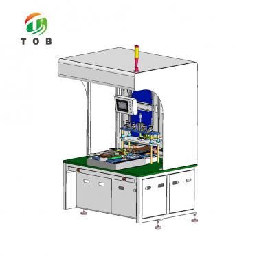
Loading...
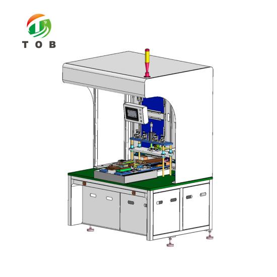
Manual Prismatic Cell Case Insertion Machine
Brand:
TOB NEW ENERGYitem no.:
TOB-MFA-200order(moq):
1Payment:
L/C,T/Tproduct origin:
Chinashipping port:
XIAMEN
Manual Prismatic Cell Case Insertion Machine
Product Overview and Ideal Applications
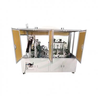
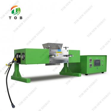
The TOB-MFA-200 is a manual case insertion machine for prismatic battery cells. The machine assists the operator in inserting the electrode stack (the stacked or wound cathode-separator-anode assembly) into the prismatic aluminum case in a horizontal orientation—the step commonly referred to in the battery industry as case insertion. The design combines manual feeding with precision positioning and a powered insertion-and-transfer mechanism, ensuring that the aluminum case is not damaged or scratched during the process and that the electrode stack is inserted cleanly and completely.
The TOB-MFA-200 operates with a production speed of ≥ 3–5 ppm (depending on operator proficiency), a pass rate of ≥ 99.95 % (referring only to product scrapping caused by equipment reasons), and a failure rate of ≤ 2 %. It is compatible with prismatic cells within a thickness range of 30–60 mm, a width range of 50–180 mm, and a height range of 100–200 mm. Within this compatibility range, cell compatibility is achieved by adjusting the tooling.
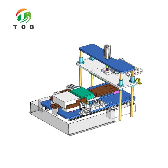
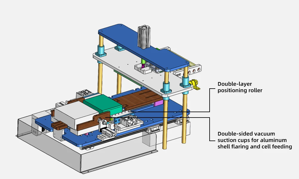
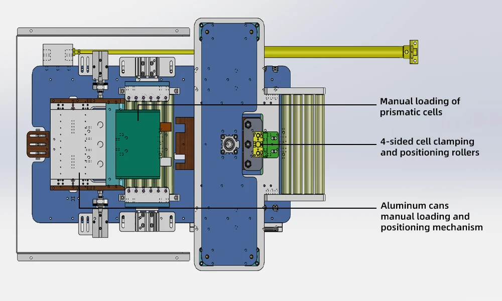
The machine is built around a feeding mechanism (manual placement of aluminum cases and electrode stacks, with positioning at all placement locations), and a case-insertion and transfer mechanism that uses soft polyurethane rollers for stack holding and positioning, a linear module for aluminum-case positioning and transfer (with travel data adjustable via the touchscreen), a suction mechanism that expands the case opening before insertion, and a case-pressing handle that allows the operator to complete the insertion manually if the stack is not fully inserted.
Ideal for:
- Prismatic aluminum-case cell production lines where the electrode stack must be inserted into the case before top-lid sealing and electrolyte filling.
- Pilot lines and small-batch production facilities that need a flexible, manual case-insertion station that can be quickly changed over between cell sizes.
- R&D laboratories assembling prismatic prototype cells, where a semi-manual insertion process provides the operator control needed to protect fragile electrode stacks.
- Cell manufacturers that require consistent, scratch-free case insertion with high pass rates.
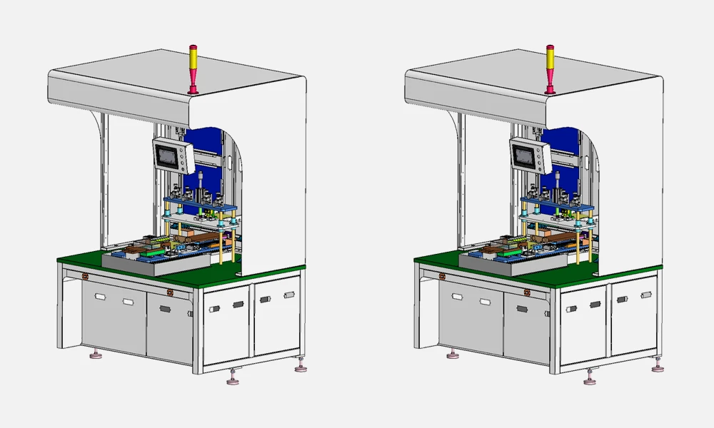
Where Case Insertion Fits in Prismatic Cell Assembly
In the manufacturing of a prismatic aluminum-case lithium-ion cell, case insertion occurs after the electrode stack is prepared and before the top lid is welded and the electrolyte is filled. The process sequence is:
- Electrode stack preparation: The cathode, separator, and anode sheets are stacked or wound to form the electrode assembly, and the tabs are attached.
- Case insertion (the TOB-MFA-200's role): The electrode stack is inserted into the aluminum case horizontally. This step must be performed carefully to avoid scratching the case interior, damaging the electrode stack, or misaligning the tabs.
- Tab welding: The cell tabs are connected to the terminal posts of the top lid or the internal current collectors.
- Top lid sealing: The top lid is laser-welded onto the case to create a hermetic seal.
- Electrolyte filling and final sealing: Electrolyte is introduced through the filling port, and the port is sealed.
The case-insertion step is quality-critical because the aluminum case has thin walls that can be dented or scratched, and the electrode stack is fragile. The TOB-MFA-200 addresses these requirements through soft polyurethane stack-positioning rollers, a suction mechanism that expands the case opening to facilitate insertion, and a manual case-pressing handle as a fallback to complete insertion if the automatic mechanism does not fully seat the stack.
Technical Specifications
The following tables contain the specifications exactly as provided for the TOB-MFA-200.
Equipment Parameters
| No. | Item | Parameter | Remark |
| 1 | Production speed | ≥ 3–5 ppm | It depends on the proficiency of the personnel |
| 2 | Outer dimension | L1500 × W1500 × H1850 mm | Subject to the actual design |
| 3 | Compatible battery cell range | T: 30–60 mm; W: 50–180 mm; H: 100–200 mm | Requirement: Within the compatibility range, battery cell compatibility can be achieved by adjusting the tooling |
| 4 | Failure rate | ≤ 2 % | Failure rate = MTTR/(MTBF+MTTR) |
| 5 | Pass rate | ≥ 99.95 % | It only refers to the scrapping of products caused by equipment reasons |
Technical Requirements for Each Part
| Part | Technical Requirement |
| Feeding mechanism |
1. Manual feeding mode is adopted, with aluminum cases and electrode stacks placed manually. 2. There are positioning mechanisms at all locations where aluminum case cells are placed. 3. During operation, the aluminum case must not be damaged or scratched. |
| Case insertion and transfer mechanism |
1. The stack positioning rollers use soft polyurethane rollers to hold and position the electrode stack. 2. The aluminum case positioning and transfer mechanism uses a linear module to move and adjust the position, with travel data adjustable via the touchscreen. 3. Before stack insertion, a suction mechanism expands the opening of the aluminum case to facilitate insertion. 4. If the stack is not fully inserted, it can be manually pushed in using a case-pressing handle to complete the insertion. |
Component Brand List
| No. | Item | Brand |
| 1 | Cylinder | AirTac |
| 2 | Magnetic valve | AirTac |
| 3 | Linear guideway | TSC / AirTac |
| 4 | Relay | OMRON |
| 5 | PLC | Panasonic |
| 6 | Touch screen | Weinview |
| 7 | Switch | MeanWell |
Remark: We reserve the right to change product brands without prior notice, provided that all specifications, quality, and performance remain unchanged.
Key Engineering Characteristics of the TOB-MFA-200
-
Manual Feeding with Precision Positioning for Case Insertion
The machine adopts a manual feeding mode in which the operator places the aluminum case and the electrode stack into the designated positions. Positioning mechanisms at all placement locations ensure that the components are correctly aligned before the case-insertion step, protecting both the case and the stack from misalignment damage. -
Soft Polyurethane Stack-Positioning Rollers
The positioning rollers are made of soft polyurethane, providing gentle, non-damaging holding and positioning of the electrode stack during the insertion process. The soft material prevents scratches and dents on the aluminum case—a key requirement for maintaining case integrity and final cell quality. -
Linear-Module Case Positioning with Touchscreen Adjustment
The aluminum-case positioning and transfer mechanism uses a linear module to move and adjust the case position. The travel data is adjustable via the touchscreen, allowing the operator to fine-tune the insertion path for different cell sizes within the compatibility range. -
Suction-Assisted Case Opening
Before stack insertion, a suction mechanism expands the opening of the aluminum case. This opens the case mouth to facilitate the clean entry of the electrode stack, reducing the risk of scratching the case interior or catching the electrode edges during insertion. -
Manual Case-Pressing Handle Fallback
If the stack is not fully inserted by the automatic mechanism, the operator can complete the insertion manually using a case-pressing handle. This fallback ensures that no partially inserted stack is lost, and it provides the operator with control for delicate or unusual stack geometries. -
Wide Cell Compatibility Range
The machine is compatible with prismatic cells in a thickness range of 30–60 mm, width of 50–180 mm, and height of 100–200 mm. Within this range, cell compatibility is achieved by adjusting the tooling, providing flexibility for different cell formats without requiring a dedicated machine for each size. -
High Pass Rate and Low Failure Rate
The specified pass rate of ≥ 99.95 % (equipment-caused scrapping only) and failure rate of ≤ 2 % demonstrate the reliability of the case-insertion process. The production speed of ≥ 3–5 ppm is suitable for both pilot and small-batch production environments.
General Equipment Requirements Summary
The TOB-MFA-200 is designed and manufactured in accordance with the comprehensive equipment requirements covering electrical safety, occupational health, dust control, and equipment TECSA principles. Key highlights include:
- Electrical safety: Air circuit breaker at the power inlet; low-voltage control circuits with standardized wiring; hardware contact interlock (software-only interlock not acceptable); protection against overload, short circuit, overvoltage, overtravel, and human-machine interference.
- Insulation and product protection: Non-metallic design for conveying surfaces, worktables, and stack positioning surfaces; copper, nickel, zinc, and cadmium materials strictly prohibited on parts that directly or indirectly contact products; no sliding dry friction between products and equipment.
- Safety protection: Door interlocks and safety light curtains (not microswitches); emergency stop buttons with anti-accidental-contact protection; protective guards fully enclosing moving parts; rounded corners on all product-contact surfaces.
- Dust control: Metal-to-metal friction prohibited in moving parts; brass, nickel, and zinc materials avoided; dust-fall prevention along product movement paths; cable trays above cells use dust-free cable chains; anti-rust treatment on all metal components.
- Appearance: Appearance color customizable; compressed air pipes black, vacuum lines transparent; flow-direction markings on secondary piping; prominent safety signs at hazard sources.
- Occupational health: Equipment noise < 80 dB measured at 1000 mm from the machine outer wall.
These general requirements are implemented per the TOB NEW ENERGY equipment standards and may be adapted according to equipment functions and specific purchaser requirements.
Practical Operation Recommendations
- Case and stack loading: Place the aluminum case and the electrode stack into their designated loading positions, guided by the positioning mechanisms. Verify that the case is clean and free of burrs or deformation before loading.
- Tooling adjustment for cell size: When changing to a different cell size within the compatibility range (T30–60, W50–180, H100–200 mm), adjust the positioning and insertion tooling to match the new dimensions. Set the linear-module travel data on the touchscreen for the new cell format.
- Insertion operation: Initiate the case-insertion sequence. The suction mechanism expands the case opening, and the linear module advances the case over the electrode stack. If the stack is not fully inserted, use the case-pressing handle to complete the insertion manually.
- Case protection: Inspect the polyurethane positioning rollers regularly for wear. Damaged or hardened rollers can scratch the aluminum case; replace them when surface degradation is observed.
- Cleaning: Keep the conveying surfaces, positioning areas, and insertion zone clean of metal dust and debris. The design follows dust-control principles, but routine cleaning is still required to maintain the pass rate.
- Touchscreen access: The HMI operation interface and the engineering interface are controlled on separate screens and protected by passwords. I/O points are displayed on the touch screen for convenient troubleshooting.
Engineering FAQ
Q1: Is the TOB-MFA-200 fully automatic or manual?
The TOB-MFA-200 is a manual case insertion machine. The feeding of aluminum cases and electrode stacks is performed manually by the operator, while the insertion and transfer mechanism is powered (linear module, suction, and polyurethane rollers assist the insertion). If the stack is not fully inserted automatically, the operator completes the insertion using the case-pressing handle. This semi-manual design provides the control and flexibility needed in R&D, pilot lines, and small-batch production.
Q2: What is the compatible cell size range?
The compatible prismatic cell range is: thickness 30–60 mm, width 50–180 mm, and height 100–200 mm. Within this range, cell compatibility is achieved by adjusting the tooling. The machine's production speed of ≥ 3–5 ppm depends on the proficiency of the operator.
Q3: How does the machine prevent scratching of the aluminum case during insertion?
Three design features protect the case: (1) the stack positioning rollers are made of soft polyurethane, which holds and positions the stack without scratching; (2) a suction mechanism expands the case opening before insertion, allowing the electrode stack to enter cleanly without catching the case edges; and (3) the positioning mechanisms at the placement locations ensure correct alignment before the insertion begins. In addition, the general equipment requirements specify non-metallic contact surfaces and prohibit sliding dry friction between the product and the equipment.
Q4: How is the insertion travel adjusted for different cell sizes?
The aluminum-case positioning and transfer mechanism uses a linear module, and its travel data is adjustable via the touchscreen. When changing to a different cell size, the operator adjusts the tooling to match the new dimensions and sets the corresponding travel data on the touchscreen interface.
Q5: What utilities does the TOB-MFA-200 require?
The machine is powered by a Panasonic PLC-controlled electrical system with OMRON relays and MeanWell switches, and uses AirTac pneumatic components (cylinders and magnetic valves) with TSC/AirTac linear guideways. The general equipment requirements specify the electrical, pneumatic, and safety standards that the machine complies with. For specific utility requirements (voltage, air pressure), contact TOB with your facility specifications.
Q6: What is the meaning of the failure rate and pass rate specifications?
The failure rate of ≤ 2 % is calculated as Failure rate = MTTR/(MTBF+MTTR), representing the ratio of repair time to total operating time. The pass rate of ≥ 99.95 % refers only to the scrapping of products caused by equipment reasons, not by operator errors or incoming material defects. These metrics define the reliability of the machine in a production environment.
Delivery Documentation
The following delivery documents are provided with the TOB-MFA-200 (all in electronic format):
| No. | Item | Quantity | Delivery Date | Remarks |
| 1 | Equipment Certificate of Conformity | 1 copy | Preliminary version before equipment arrival; final version before final acceptance | Electronic format |
| 2 | Equipment Operation Manual | 1 copy | After equipment FAT and before arrival | Electronic format |
| 3 | Equipment Maintenance Manual | 1 copy | After equipment FAT and before arrival | Electronic format |
| 4 | Equipment Overhaul Manual | 1 copy | After equipment FAT and before arrival | Electronic format |
| 5 | General Assembly Drawing | 1 copy | After equipment FAT and before arrival | Electronic format |
| 6 | Pneumatic/Hydraulic/Electrical Schematic Diagrams | 1 copy | After equipment FAT and before arrival | Electronic format |
| 7 | List of Wearing Standard Parts | 1 copy | After equipment FAT and before arrival | Electronic format |
| 8 | List of Spare Parts | 1 copy | After equipment FAT and before arrival | Electronic format |
| 9 | Changeover List | 1 copy | After equipment FAT and before arrival | Electronic format |
| 10 | Changeover Operation Instruction | 1 copy | After equipment FAT and before arrival | Electronic format |
Quality Assurance and After-Sales Service
- Warranty period: 1 year from the date of passing formal acceptance. During this period, TOB is responsible for free equipment repair and maintenance, including replacement of all components (excluding consumables). Malfunctions caused by human factors or force majeure are not covered by the warranty.
- Response time: After-sales service personnel respond within 2 hours after receiving notification from the buyer.
- After warranty: TOB continues to provide equipment repair and maintenance, charging only reasonable labor and transportation fees. Parts replacement and purchase are charged at parts cost only.
- Technical improvements: Subsequent technical improvements and new functions introduced after purchase are not covered by the warranty.
Ready to add a reliable, scratch-free case insertion step to your prismatic cell assembly line? Request a quotation for the TOB-MFA-200, including tooling for your specific cell format within the compatibility range. Our production-equipment engineers can provide a technical proposal and changeover-tooling recommendation.
tob.amy@tobmachine.com | +86 181 2071 5609
You May Also Need
▶ Prismatic Cell Casing Materials — A full range of prismatic aluminum cell casings in multiple sizes. Complements the TOB-MFA-200 by supplying the aluminum cases into which the electrode stacks are inserted on this machine.
▶ Manual Cells Feeding Machine for Prismatic Cell — A manual cell feeding machine for prismatic cell production. Complements the TOB-MFA-200 upstream, assisting in the feeding and handling of prismatic cells or stacks before the case-insertion step.
▶ Laser Welding Machine for Prismatic Cell Top Lid and Filling Port Sealing — A laser welding machine for sealing the top lid and filling port of prismatic cells. Complements the TOB-MFA-200 downstream, completing the hermetic sealing of the cell after case insertion.
If you are interested in our products and want to know more details,please leave a message here,we will reply you as soon as we can.

 subscribe to us