Chinese
 français
 Deutsch
 italiano
 español
 português
 Nederlands
 日本語
日本語 한국의
한국의




- Home
- >
- Battery Tester
- >
- Battery and Supercapacitor Capacity Tester
- >
- 8-Channel 5V6A Battery Testing System
Categories
Hot Products
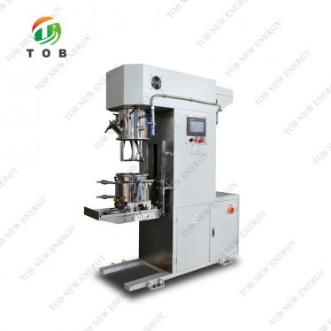
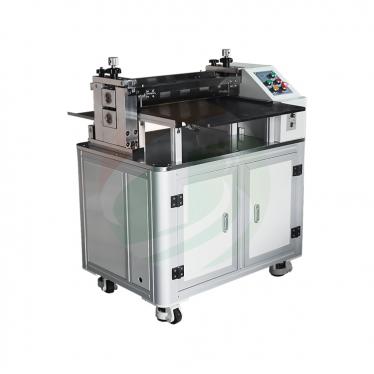
Loading...
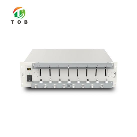
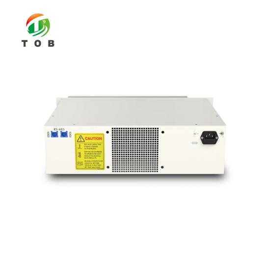
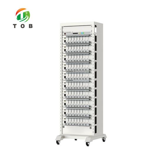
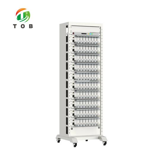
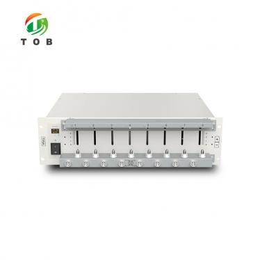
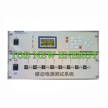
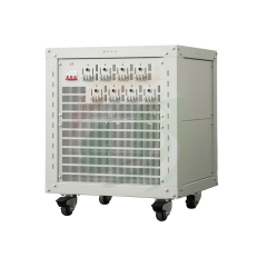
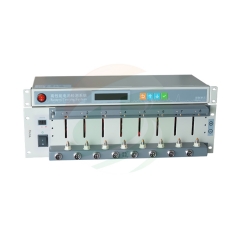
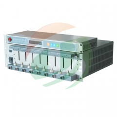
8-Channel 5V6A Battery Testing System
Brand:
TOB NEW ENERGYitem no.:
TOB-CT-4008Q-5V6A-S1order(moq):
1setPayment:
L/C,T/Tproduct origin:
Chinashipping port:
XIAMEN
8-Channel 5V6A Battery Testing System for Lithium-Ion Cell Cycling and Capacity Grading | TOB-CT-4008Q-5V6A-S1
Product Overview and Ideal Applications
The TOB-CT-4008Q-5V6A-S1 is a multi-channel battery testing system designed for charge-discharge cycling, capacity grading, DCIR measurement, and pulse testing of lithium-ion cells within a 5 V / 6 A / 30 W per-channel operating envelope. The system provides independent control on every channel, with each channel built around a dual closed-loop structure - one loop for the constant current source and one for the constant voltage source - and four-wire data acquisition that eliminates the influence of lead and contact resistance on the measured voltage.
The channels operate across four switchable current ranges - 100 mA, 500 mA, 3 A, and 6 A - with a minimum output current of 0.2 mA. This range structure gives the system a wide dynamic range: low-current characterization at the milliampere level, and full 6 A cycling for cells that demand it, without changing hardware. Voltage output spans 25 mV to 5 V, covering the full operating window of lithium-ion single cells. The measurement chain uses 24-bit AD and 16-bit DA conversion, with current response time within 1 ms and charge-to-discharge conversion time within 40 ms; data is recorded at a 10 Hz frequency (100 ms minimum interval).
Beyond basic cycling, the TOB-CT-4008Q-5V6A-S1 supports DCIR testing and pulse charge/discharge programs - in current or power mode, with a minimum pulse width of 500 ms and up to 32 pulses per step. On the software side, test data is managed through a MySQL database over a TCP/IP connection, with exports in EXCEL, TXT, GRAPH, PDF, and CSV formats. Optional CAN and RS485 communication - including BMS communication with DBC configuration - allows the system to exchange data with battery management systems for pack-level and BMS-integrated testing programs.
Ideal for:
- Battery cell manufacturers performing capacity grading, sorting, and cycle-life testing of cylindrical cells (including 18650, 21700, and 26650 formats) and pouch cells within the 5 V / 6 A / 30 W limits.
- Battery R&D laboratories evaluating electrode materials and cell designs across four current ranges, from low-current characterization to 6 A cycling, on one instrument.
- Quality-control and incoming-inspection laboratories that require traceable test data with database management and standardized export formats.
- Pack and BMS developers using the optional CAN / RS485 / BMS communication interface to test cells and packs with real-time BMS data exchange.
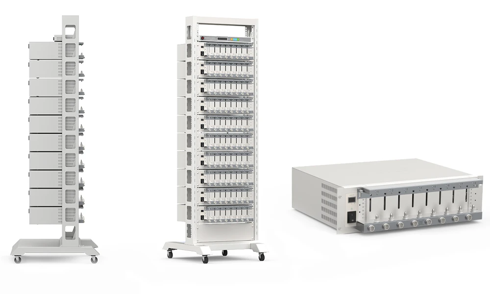
Where Battery Testing Fits in Cell Manufacturing and R&D
In the lithium-ion cell manufacturing chain, cell-level charge-discharge testing serves two principal roles:
- Capacity grading and sorting (production): After formation, cells are cycled to measure their actual capacity, internal resistance, and self-discharge characteristics, and are sorted into capacity bins. Grading determines which cells are matched into a battery pack - a step that directly affects pack performance and life. The TOB-CT-4008Q-5V6A-S1 performs this function for cells within its power envelope, with independent channel control allowing multiple cells to be graded in parallel.
- Performance and life testing (R&D and QC): During development and quality verification, cells are cycled under controlled protocols to measure capacity retention, rate capability, and DCIR growth. The four-range architecture means the same system can run a low-rate characterization and a high-rate cycling program without switching equipment.
The system's DCIR function supports internal-resistance measurement under load - a key parameter for power-capable cells - while the pulse charge/discharge program supports protocols that emulate real-world load profiles. For teams working with battery management electronics, the optional BMS communication interface extends testing from the bare cell to the pack level, with DBC configuration enabling message-level integration.
Key Engineering Characteristics of the TOB-CT-4008Q-5V6A-S1
- Independent Multi-Channel Control with Dual Closed-Loop Sources - Each channel pairs an independent constant current source and constant voltage source in a dual closed-loop structure, with independent channel control. This architecture holds voltage or current precisely during the transition between CC and CV phases - the critical point of any charge protocol. Channel parallelism is not supported, so channels are applied to individual cells.
- Four Current Ranges from 100 mA to 6 A - The 100 mA / 500 mA / 3 A / 6 A range structure, combined with a 0.2 mA minimum output current, gives the testing system a wide dynamic range. Small cells and low-current characterization tests run on the low ranges; 6 A cycling - sufficient for high-capacity cylindrical cells - runs on the top range, with CV cut-off currents scaled per range (0.1 mA / 0.5 mA / 3 mA / 6 mA).
- Four-Wire Data Acquisition - Voltage and current detection use a four-wire (Kelvin) connection, separating the current-carrying path from the voltage-sensing path. This preserves measurement accuracy at the cell terminals regardless of lead and contact resistance - a fundamental requirement for accurate capacity and DCIR data.
- 24-Bit AD / 16-Bit DA Measurement Chain - The 24-bit AD and 16-bit DA conversion, with voltage and current accuracy of ± 0.01 % of FS and power accuracy of ± 0.02 % of FS, provide the resolution and repeatability needed for reliable grading. Data is recorded at 10 Hz (100 ms minimum interval), and current response time is within 1 ms (10 % ~ 90 % of FS) with charge/discharge conversion within 40 ms (-90 % ~ 90 % of FS).
- Pulse Testing and DCIR - Pulse charge/discharge programs run in constant current or constant power mode, with a minimum pulse width of 500 ms and up to 32 pulses per step, and cut-off by voltage or relative time. DCIR testing is supported, enabling internal-resistance measurement under defined current pulses.
- Comprehensive Protection, Software and Hardware - Software protection allows settable safety conditions - voltage upper/lower limits, current upper/lower limits, and additional parameters - while hardware protection covers anti-reverse connection, over-voltage, over-current, and over-temperature. These layers protect both the cells under test and the instrument during long-duration cycling.
- Database-Managed Data with Standard Export Formats - Test data is managed through a MySQL database with TCP/IP host communication. Results are exportable in EXCEL, TXT, GRAPH, PDF, and CSV formats, supporting quality documentation and downstream analysis.
- Optional CAN / RS485 / BMS Communication - An optional communication expansion supports CAN and RS485 communication, including BMS communication with DBC configuration - extending the testing system to programs where the battery management system participates in the test.
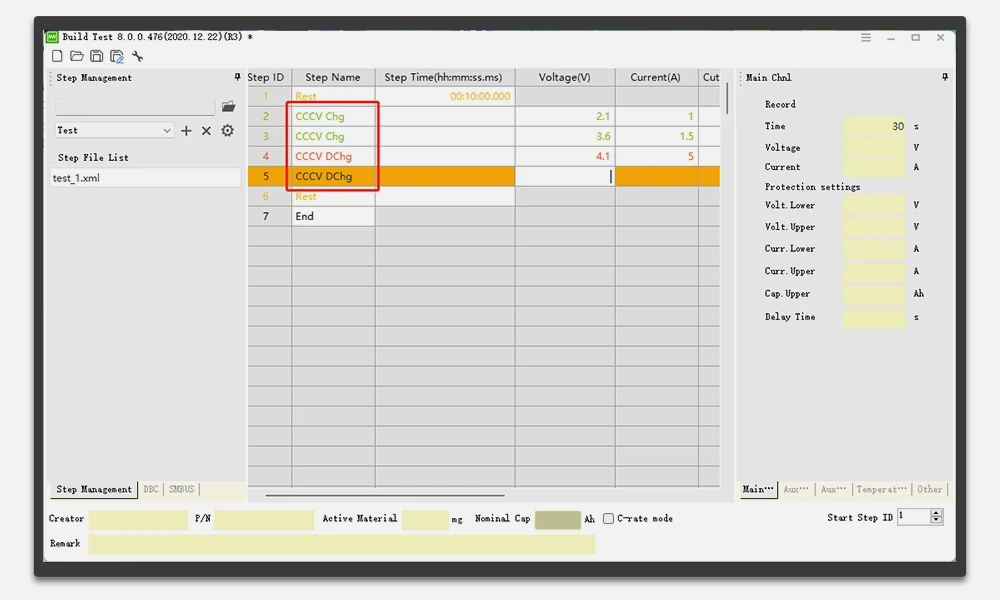
Technical Specifications
1. General
| Item | Value |
| Input power | AC 220 V ± 10 % / 50 Hz |
| Input power | 450 W |
| Resolution | AD: 24-bit; DA: 16-bit |
| Input resistance | ≥ 1 MΩ |
| Overall system efficiency | Not |
| Noise | < 85 dB (measured at 1 m) |
| Parallel ability | Channel parallelism is not supported |
| IP Level | IP20 |
| Channels feature | Independent pairs of closed loop for constant current source and constant voltage source |
| Channels control mode | Independent control |
| Data acquisition | Four-wire connection |
2. Voltage
| Item | Parameter |
| Output range | 25 mV - 5 V |
| Min discharge voltage | Upper and lower fixture 1 V, 2 m line length 1.5 V |
| Accuracy | ± 0.01 % of FS |
| Stability | 0.02 % of FS |
3. Current
| Item | Parameter |
| Output range | Range 1: 100 mA; Range 2: 500 mA; Range 3: 3 A; Range 4: 6 A |
| Accuracy | ± 0.01 % of FS |
| Minimum output current | 0.2 mA |
| CV cut-off current | Range 1: 0.1 mA; Range 2: 0.5 mA; Range 3: 3 mA; Range 4: 6 mA |
| Stability | 0.02 % of FS |
4. Power
| Item | Parameter |
| Single channel output power | 30 W |
| Accuracy | ± 0.02 % of FS |
| Stability | 0.04 % of FS |
5. Time
| Item | Parameter |
| Current response time | ≤ 1 ms (10 % ~ 90 % of FS) |
| Current conversion time | ≤ 40 ms (-90 % ~ 90 % of FS) |
| Working step time | ≤ (365 x 24) h/step; time format 00:00:00.000 (h, m, s, ms) |
| Frequency | 10 Hz (minimum time interval: 100 ms) |
6. Working Mode
| Item | Parameter |
| Charge/Discharge modes | CC, CV, CCCV, CP, Pulse, etc. |
| Cut-off condition | Voltage, current, time, capacity, energy, etc. |
| DCIR | Supported |
| Pulse charge/discharge mode | Current, Power |
| Min pulse | 500 ms |
| Pulse counts | Up to 32 |
| Chg and Dchg switch | unsupported |
| Cut-off condition | Voltage, Delta Time |
7. Cycle
| Item | Parameter |
| Max cycles | 1 - 65535 |
| Max steps | ≤ 255 |
| Cycle nest | < 10 |
8. Protection Mode
| Item | Parameter |
| Software protection | Safety protection conditions can be set, including: voltage lower limit, voltage upper limit, current lower limit, current upper limit, etc. |
| Hardware protection | Anti-reverse connection, over-voltage, over-current, over-temperature, etc. |
9. Communication and Computer Configuration Requirements
| Item | Requirement |
| CPU | Pentium dual-core or above, frequency 4G or above |
| Computer memory | Recommended 16G or above |
| Connection for PC | TCP/IP |
| Disk drive config | Min. 500GB |
| PC operating system | Windows 7 and above |
| Database | MySQL |
| Data export format | EXCEL, TXT, GRAPH, PDF, CSV |
| Communication expansion (optional) | Support CAN, RS485 communication and BMS communication, with DBC configuration function |
10. Operation and Storage Environment Requirement
| Item | Parameter |
| Operating temperature | 0 °C ~ 40 °C (when the temperature is 25 ± 10 °C, the accuracy offset caused by temperature is less than 50 ppm/°C) |
| Storage temperature | -10 °C ~ 50 °C |
| Operating humidity | ≤ 70 % RH (no moisture condensation) |
| Storage humidity | ≤ 80 % RH (no moisture condensation) |
11. Fixture specifications and equipment dimensions
| Clamp types | Optional (to be clearly marked during order confirmation) | ||
| Clamps pictures(For reference only) | Alligator | Polymer | Ring Connector |
| Channel | 8 | ||
| Dimension W*D*H(mm) | 3U(19"), 483*404*130 | ||
Practical Testing Recommendations
- Wiring and fixtures: Connect cells using the specified four-wire scheme to preserve voltage measurement accuracy. Per the specification, the minimum discharge voltage achievable depends on the connection - 1 V with the upper and lower fixture, 1.5 V with a 2 m line length - so keep the connecting leads at the specified length and avoid unnecessary extension.
- Range selection: Select the current range that matches the test plan. Low-current characterization and small cells belong on Range 1 (100 mA); 6 A cycling belongs on Range 4, where the CV cut-off current scales to 6 mA accordingly.
- Protection setup: Configure the software protection conditions - voltage upper/lower limits and current upper/lower limits - before starting long-duration cycling, so an anomalous cell is cut off automatically rather than damaging the channel or the cell.
- Pulse and DCIR programs: For pulse testing, note the 500 ms minimum pulse width and the 32-pulse limit per step; pulse steps are cut off by voltage or relative time. DCIR measurement should be run under consistent current and timing conditions to make results comparable between cells and batches.
- Data management: Operate the system through the TCP/IP host connection and back up the MySQL database periodically. Export data in EXCEL, TXT, GRAPH, PDF, or CSV formats per your quality-records requirements.
- BMS-integrated testing (optional): When using the optional CAN / RS485 / BMS communication, prepare the DBC configuration file so that BMS messages are correctly interpreted by the test software.
Engineering FAQ
Q1: What types of cells can the TOB-CT-4008Q-5V6A-S1 test?
Any cell that operates within the system's envelope: up to 5 V and 6 A per channel, with a maximum single-channel output power of 30 W. This covers most single-cell testing applications - cylindrical cells such as 18650, 21700, and 26650 formats, and pouch cells - as well as low-current characterization on the 100 mA range thanks to the 0.2 mA minimum output current. Channel parallelism is not supported, so each channel is used for one independent cell.
Q2: What is the benefit of the four current ranges?
A single range cannot serve both milliampere-level characterization and 6 A cycling with good accuracy. The 100 mA / 500 mA / 3 A / 6 A structure lets the testing system run each test on the range where the measurement is most accurate - with CV cut-off currents scaled per range (0.1 mA to 6 mA) - so one instrument covers everything from small-cell evaluation to full 6 A cycling.
Q3: What pulse and DCIR capabilities does the system support?
Pulse charge/discharge programs can run in constant current or constant power mode, with a minimum pulse width of 500 ms and up to 32 pulses per step, cut off by voltage or relative time. DCIR testing is supported, providing internal-resistance data for power-capability evaluation and grading.
Q4: Can the system test battery packs or communicate with a BMS?
The optional communication expansion supports CAN and RS485 communication, including BMS communication with DBC configuration. This allows test programs in which the battery management system participates - defined by the customer's BMS protocol and the DBC file - while the base system continues to perform cell-level charge-discharge, pulse, and DCIR testing.
Q5: How is test data managed?
Test data is stored in a MySQL database managed by the host software, connected over TCP/IP, with exports in EXCEL, TXT, GRAPH, PDF, and CSV formats. Software protection conditions (voltage and current limits) are settable in the same environment, and hardware protection - anti-reverse connection, over-voltage, over-current, and over-temperature - operates independently.
Q6: What operating conditions does the system require?
Operating temperature 0 °C ~ 40 °C and operating humidity ≤ 70 % RH without moisture condensation; storage at -10 °C ~ 50 °C and ≤ 80 % RH. Within 25 ± 10 °C, the accuracy offset caused by temperature is less than 50 ppm/°C. The system is rated IP20 and should be installed in a clean, dry, well-ventilated location.
Ready to add reliable, multi-channel cell cycling and grading capacity to your laboratory or production QC line? Request a quotation for the TOB-CT-4008Q-5V6A-S1, specifying your cell format, test protocol, and whether the optional CAN / RS485 / BMS communication is required. Our battery testing engineers can advise on fixture selection and test-program setup.
tob.amy@tobmachine.com | +86 181 2071 5609
You May Also Need
▶ Four-Zone Constant Temperature Environmental Test Chamber for Coin Cell Testing - A four-zone constant-temperature test chamber for coin cell programs. Complements the TOB-CT-4008Q-5V6A-S1 when testing must be carried out under controlled temperature conditions.
▶ Lithium-Ion Battery Tester Constant Temperature Test System - A battery testing system with integrated constant-temperature control. Provides an alternative configuration where temperature-conditioned testing is integrated in a single system.
▶ 5V5A Lithium-Ion Battery Testing Equipment - Lithium-ion battery testing equipment in a 5 V / 5 A class. A related TOB testing platform for customers whose current requirements fit a different power class.
If you are interested in our products and want to know more details,please leave a message here,we will reply you as soon as we can.

 subscribe to us