Chinese
 français
 Deutsch
 italiano
 español
 português
 Nederlands
 日本語
日本語 한국의
한국의




- Home
- >
- Pouch Cell Assembly Equipment
- >
- Pouch Cell Formation and Grading Machine
- >
- Energy-Feedback Battery Formation and Grading System | TOB-EF256-6G
Categories
Hot Products
Loading...
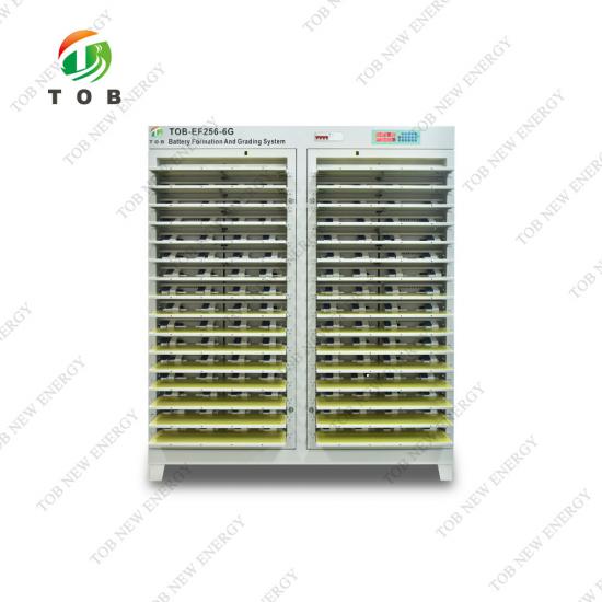
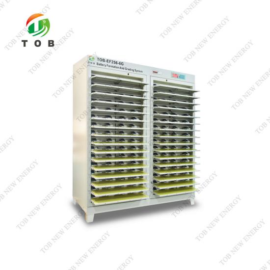
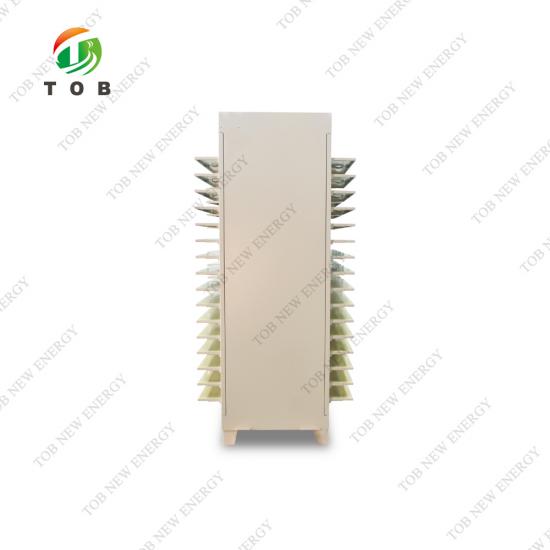
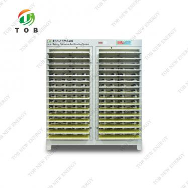
Energy-Feedback Battery Formation and Grading System | TOB-EF256-6G
Brand:
TOB NEW ENERGYitem no.:
TOB-EF256-6Gorder(moq):
1setPayment:
L/C,T/Tproduct origin:
Chinashipping port:
XIAMEN
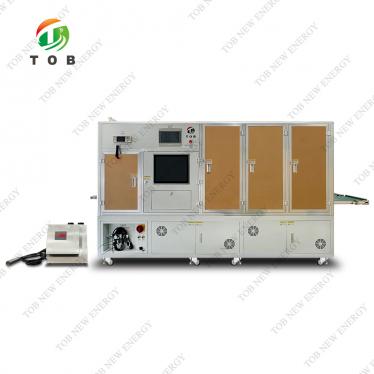
TOB-EF256-6G Energy-Feedback Automatic Formation and Grading System for Pouch Cells
Product Overview and Ideal Applications
The TOB‑EF256‑6G is an automatic formation and grading system purpose‑built for rechargeable lithium‑ion pouch cells. It combines 256 independent test channels—each capable of charging and discharging at up to 6 A within a 0–5 V voltage window—with a bidirectional AC‑DC/DC‑AC energy‑feedback power architecture that routes the energy discharged from cells back into the factory's AC mains rather than dissipating it as heat. This design simultaneously delivers high‑precision electrochemical cycling and a substantial reduction in the electrical energy consumption of a battery production line.
Every channel on the TOB‑EF256‑6G uses a true four‑wire (Kelvin) measurement scheme and is driven by a dedicated constant‑current/constant‑voltage source that is electrically isolated from its neighbours. The entire 256‑channel cabinet is controlled as a single unit via Ethernet or RS‑485 from a Windows‑based host computer running TOB's proprietary formation software. The software allows the user to program up to 32 steps and 256 cycles per recipe, with each step selectable as constant‑current charge, constant‑voltage charge, constant‑current discharge, or rest. Real‑time voltage/current/capacity/energy curves are plotted for every channel, and all raw data plus end‑of‑step results are saved locally and optionally uploaded to a server database for MES integration.
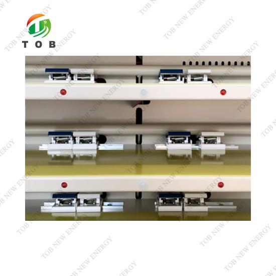
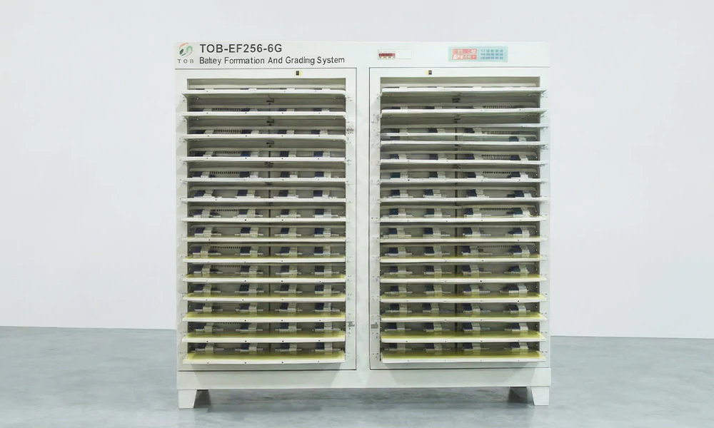
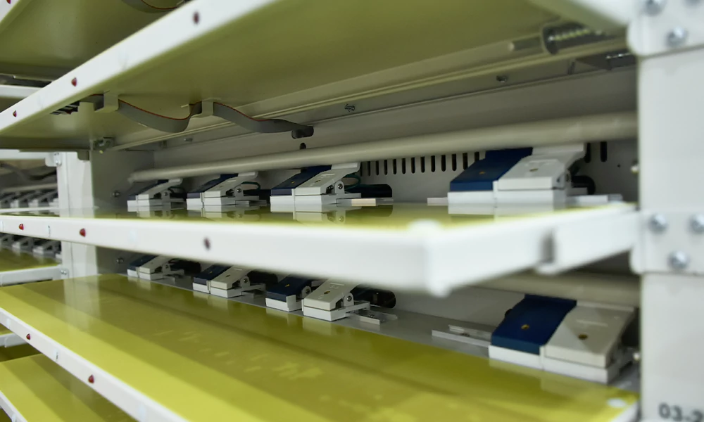
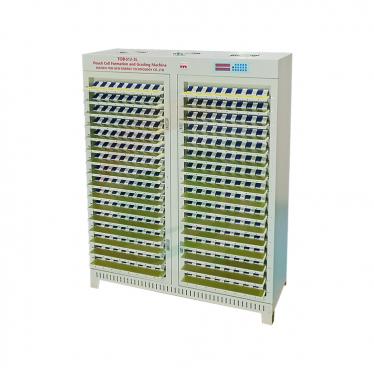
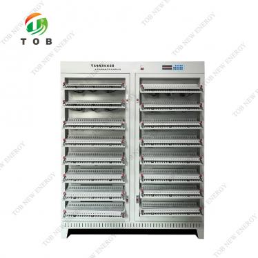
The mechanical design of the TOB‑EF256‑6G is tailored to the handling of pouch cells. The cabinet is divided into four doors, each containing 16 layers of fixtures arranged for cells loaded on both sides of the tray. A motor‑driven vertical clamping mechanism opens and closes the entire bank of fixtures simultaneously, speeding up cell loading and unloading. The fixture trays are of a split design, with adjustable positive‑ and negative‑electrode contact spacing that can accommodate pouch cells with tabs up to 120 mm apart.
Ideal for:
- Lithium‑ion pouch‑cell production lines performing the critical formation (first charge, SEI build‑up) and capacity grading steps before cells are assembled into modules or shipped as finished products.
- Battery pilot lines that need a single cabinet capable of processing up to 256 cells per batch with the same electrical precision and data traceability as a full‑scale production system.
- Manufacturers seeking to reduce the electrical operating cost of their formation area by deploying energy‑feedback systems that recover a significant fraction of the discharge energy.
- Quality‑control departments that require a permanent, auditable digital record of every cell's formation and grading data, from initial open‑circuit voltage to final capacity bin.
Where Formation and Grading Fit in Pouch‑Cell Manufacturing
The formation and grading step sits between cell assembly and final shipment, and it serves two distinct purposes:
- Formation: A freshly assembled pouch cell contains a dry separator and a pristine set of electrodes. When the first charge is applied, the electrolyte decomposes in a controlled manner at the anode surface, forming the solid‑electrolyte interphase (SEI). This SEI is essential for the cell's long‑term stability, but it consumes a small amount of lithium and generates gas. The formation protocol—a carefully defined sequence of charge‑currents, voltage holds, rest periods, and sometimes a degassing step—must be executed with high accuracy and repeatability, because variations in the formation voltage or current can lead to uneven SEI growth and a wide spread in cell capacity and internal resistance.
- Grading: After formation, each cell is discharged and recharged (often for one or more cycles) to measure its actual capacity, energy, and internal resistance. The cells are then sorted into capacity bins (typically within ±1 % of a target capacity) so that cells assembled into the same module or pack have closely matched electrical characteristics. The TOB‑EF256‑6G supports multiple grading strategies, including capacity grading, time grading, capacity‑plus‑curve grading, time‑plus‑curve grading, capacity‑plus‑voltage grading, and fixed‑voltage grading, giving the production engineer the flexibility to choose the method that best correlates with field performance.
By combining formation and grading in a single 256‑channel cabinet, the TOB‑EF256‑6G reduces cell handling: the same fixture holds the cell from the first formation charge through the final grading discharge, eliminating the need to transfer cells between machines and reducing the risk of tab damage or contamination.
How the Energy‑Feedback System Works
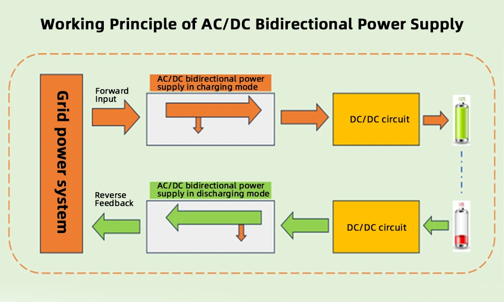
The TOB‑EF256‑6G uses a bidirectional AC‑DC/DC‑AC power architecture that fundamentally changes how electrical energy flows during cell cycling:
During charge:
- Each channel's constant‑current/constant‑voltage source draws DC power from an internal 14 V DC bus, which is supplied by the AC‑DC stage of the bidirectional power supply.
- The AC‑DC stage converts AC mains electricity (three‑phase, 380 V) into regulated DC with a conversion efficiency that is inherently higher than that of a traditional linear constant‑current source.
- The overall energy flow during charge is: (Grid electricity + energy from other cells that are simultaneously discharging) → AC‑DC bidirectional inverter → DC bus → per‑channel DC‑DC circuit → cell.
During discharge:
- The cell's stored energy is fed back through the per‑channel DC‑DC circuit, which boosts the cell voltage to the internal DC bus voltage.
- The DC‑AC stage of the bidirectional power supply then inverts this DC energy into AC and synchronises it with the factory's AC grid.
- The AC power flows onto the factory's local AC bus, where it is preferentially consumed by other equipment—including other TOB‑EF256‑6G cabinets that are charging cells, plus general factory loads such as lighting, HVAC, and office equipment.
- Only the energy that exceeds the factory's instantaneous consumption is exported back to the wider electricity grid.
Efficiency specifications:
- Charging power‑supply output conversion efficiency: > 70 % (calculated as software‑recorded battery charge energy divided by the electrical meter's measured consumption × 100 %).
- Discharge power‑supply feedback efficiency: > 65 % (calculated as the electrical meter's reverse active energy divided by the software‑recorded battery discharge energy × 100 %).
These efficiency figures mean that for every 1 kWh of energy discharged from cells during capacity testing, approximately 0.65 kWh is recovered and re‑used within the factory, rather than being dissipated as heat through resistive load banks.
Key System Capabilities
▶ 256 Independent, Isolated Channels
Each of the 256 channels has its own constant‑current/constant‑voltage source that is electrically isolated from the others. The per‑channel current range is 5–6000 mA, covering the formation needs of small pouch cells (e.g., 150 mAh) to larger pilot‑production cells. All channels are addressed and controlled as a group by the cabinet controller, but each channel's electrical circuit is completely independent, so a fault on one channel does not affect the others.
▶ High Measurement Accuracy with Four‑Wire Kelvin Connection
The current accuracy is ±0.05 % of full scale plus ±0.05 % of reading, and the voltage accuracy is ±2 mV. These specifications are enabled by the true four‑wire measurement method, which separates the current‑carrying leads from the voltage‑sensing leads at the fixture contact point, eliminating the contribution of lead resistance and contact resistance from the measured cell voltage. A full‑cabinet scan of all 256 channels is completed within ≤ 3 s, and the minimum data recording interval is 5 s.
▶ Modular Construction with Motorised Automatic Clamping
The cabinet is divided into four doors, each with 16 layers of fixtures (256 channels total). Cell loading and unloading is accelerated by a motor‑driven vertical clamping mechanism that opens or closes all fixtures in a door simultaneously. The fixture trays are of a split design: the positive and negative contact assemblies can be moved independently, adjusting the contact spacing up to a maximum of 120 mm to accommodate pouch cells with different tab separations. The point‑to‑point contact spacing along each tray is 168 mm.
▶ Energy‑Feedback Architecture Reduces Operating Cost
The bidirectional AC‑DC/DC‑AC power supply recovers a substantial fraction of the discharge energy that would otherwise be wasted. In a typical formation and grading protocol where the cells are discharged multiple times for capacity measurement, the recovered energy directly reduces the factory's electricity bill and lowers the heat load on the factory's air‑conditioning system.
▶ Flexible, Multi‑Step Recipe Programming
The host software, running on a Windows PC connected via Ethernet or RS‑485, allows up to 32 steps and 256 cycles to be programmed per recipe. Each step can be configured as constant‑current charge, constant‑voltage charge, constant‑current/constant‑voltage charge, constant‑current discharge, or rest. A step can be terminated on current, voltage, time, or capacity conditions. This flexibility supports complex formation protocols, such as multi‑stage wetting, gas‑formation, and degassing sequences.
▶ Comprehensive Data Logging and MES Connectivity
Detailed raw data for every channel and every step is saved locally to the PC as individual process files. End‑of‑step results (open‑circuit voltage, average voltage, step time, current, capacity, plateau capacity) are stored in a standard MDB database file, one per process run. In facilities with a configured data server, the results can be automatically uploaded to a server database, where the MDB files serve as a standard database format that can be directly integrated with a factory MES. This architecture preserves a complete digital record for traceability and supports the statistical analysis needed for continuous process improvement.
▶ Barcode Scanning for Cell Traceability
The TOB‑EF256‑6G supports barcode scanning, including sequential scanning and channel‑jump scanning, so that each cell's unique bar‑code is bound to the specific channel in which it is processed. The bar‑code data is stored with the formation and grading results, enabling full forward‑and‑backward traceability from incoming cells to final capacity bins.
▶ Comprehensive Protection and Alarm Functions
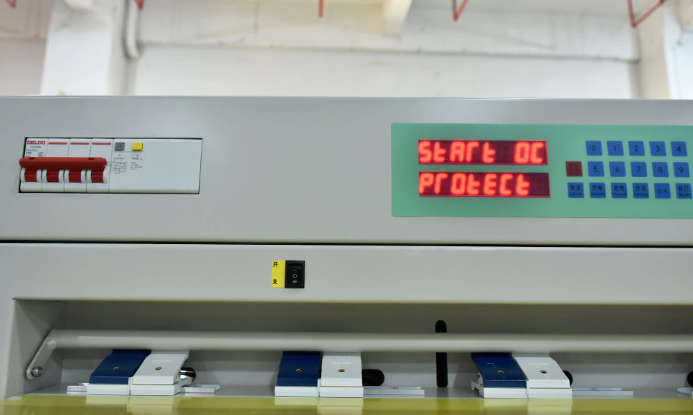
The system protects cells and the equipment itself through hardware‑ and software‑based safeguards: over‑current, under‑current, over‑voltage, under‑voltage, over‑capacity, and leakage‑current detection. Charge over‑voltage and discharge under‑voltage are protected by both a hardware circuit and a software limit, providing a redundant safety layer that protects cells even if the control software were to malfunction.
Technical Specifications
|
Specification |
Parameter |
Specification |
Parameter |
|
Number of channels |
256 channels |
Control method |
Whole cabinet control |
|
Working power supply |
Three-phase five-wire AC380±10% 50HZ |
Total power (KW) |
≤9 |
|
Communication method |
Ethernet/RS485 |
Whole cabinet scanning speed |
≤3s |
|
Charging/Discharging current range |
5-6000 (mA) |
Current accuracy |
±0.05%FS+0.05%RD |
|
Current resolution |
0.1 (mA) |
Voltage measurement range |
0-5V |
|
Voltage resolution |
0.1 (mV) |
Charging voltage range |
0-4.5V |
|
Discharging voltage range |
2-4.5V |
Voltage accuracy |
±2 (mV) |
|
Time measurement range |
999/step (min) |
Time accuracy (min) |
±0.1% |
|
Maximum step setting number |
32 steps |
Maximum cycle setting number |
256 times |
|
Accuracy calibration cycle |
6 months |
Calibration method |
Software digital calibration |
|
Set step content |
Constant current charge, constant voltage charge, constant current constant voltage charge, constant current discharge, rest (standby) |
||
|
Step end condition |
Current, voltage, time, capacity |
||
|
Protection methods |
Over-current, under-current, over-voltage, under-voltage, over-capacity, leakage current. Among them, charging over-voltage/discharging under-voltage adopt both hardware and software dual protection |
||
|
Curve display |
Charge/discharge current curve, charge/discharge voltage curve, charge/discharge capacity curve |
||
|
Grading methods |
Capacity grading, time grading, capacity + curve grading, time + curve grading, capacity + voltage grading, fixed-point voltage grading |
||
|
Data statistics |
For each cell each step: open circuit voltage, average voltage, working time, current, capacity, plateau capacity; detailed curves and data for each step, statistics of cell counts in each capacity segment, etc. |
||
|
Energy-saving feedback efficiency |
The charging and discharging power supply adopts AC-DC/DC-AC energy-saving power supply, and the discharge energy of the cells is fed back to the grid. The charging power supply output conversion efficiency is >70% (calculated as: battery charging capacity from software / meter power consumption ×100%). The discharge power supply feedback efficiency is >65% (meter reverse active power / battery discharge capacity ×100%). |
||
Additional Functional Specifications
| Function | Description |
| Barcode Scanning | Supports barcode scanning with sequential and channel‑jump modes; binds barcode to channel information for traceability. Wireless barcode scanner supplied by the customer according to their barcode format. |
| Local Data Storage | Detailed process data saved locally without deletion, one file per process run. Files can be copied to other PCs for viewing. |
| Local Results Storage | End‑of‑step results saved locally as MDB files, one per process run. MDB files contain only the end‑of‑step data. |
| Server Data | With a configured data server, results can be uploaded to a server database. Retention period configurable according to customer requirements. MDB format is standard and can interface with MES. |
Mechanical Specifications
| Parameter | Specification |
| Clamping Method | Motor‑driven, whole‑door simultaneous vertical clamping; double‑sided cell placement |
| Cabinet Layout | 256 channels, 4 doors, 16 layers per door; layer height 89 mm; top layer ground clearance 1604 mm, bottom layer ground clearance 267 mm |
| Fixture Design | Split‑type tray; tray length 676 mm, outer tray width 158 mm; true four‑wire split‑type fixture; positive/negative fixture spacing adjustable up to 120 mm; point‑to‑point contact spacing 168 mm |
| Approximate Dimensions | W 1600 mm × D 878 mm (incl. tray extension) × H 1840 mm |
System Composition
The TOB‑EF256‑6G formation and grading system as supplied comprises the following major elements:
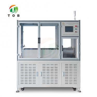
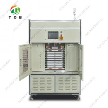
- Lithium‑ion battery formation and grading equipment (the 256‑channel cabinet described above).
- Host computer with USB and Ethernet interfaces.
- Communication converters and cables (USB‑to‑RS‑485 converter and communication cable, or Category‑5 network cable and RJ45 connectors).
- TOB formation and grading software for Windows.
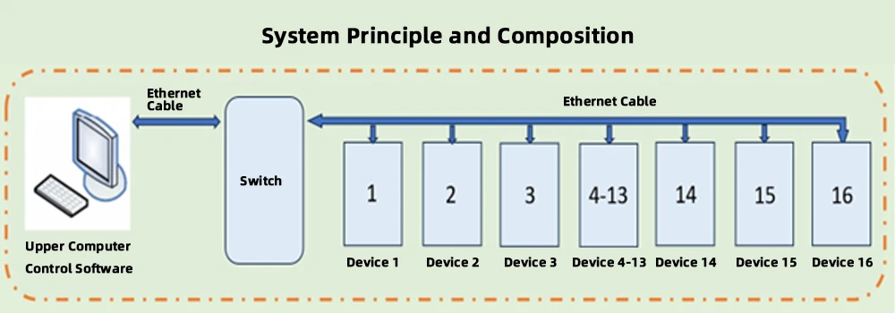
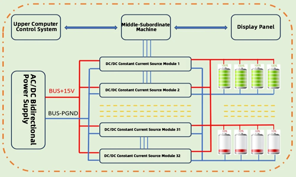
The host computer connects to the cabinet controller and sends commands while collecting data from all channels. The per‑channel constant‑current/constant‑voltage boards respond to the controller's CPU, providing constant‑current and constant‑voltage control during both charge and discharge.
During charge, the bidirectional power supply converts AC mains electricity to a 14 V DC bus, and each channel's board regulates the current to the cell. During discharge, the process is reversed: each channel's board first boosts the cell voltage to the internal DC bus, and the bidirectional power supply then inverts that DC power into AC that is fed onto the factory's AC distribution grid. This architecture achieves the energy‑feedback function described in the specifications.
Practical Operation and Maintenance Recommendations
- Calibration: The instrument's voltage and current channels should be recalibrated every 6 months using the built‑in digital calibration procedure. The calibration is entirely software‑based; no potentiometers need to be adjusted inside the cabinet. A certified digital multimeter is required as the reference standard.
- Fixture contact maintenance: The four‑wire Kelvin contacts on each fixture should be inspected periodically for wear, contamination, or oxidation. A dirty voltage‑sensing contact will produce an erroneously high voltage reading and lead to an incorrect capacity result. Clean the contacts with isopropyl alcohol and a lint‑free wipe when the cabinet is not in operation.
- Energy‑feedback operation: The energy‑feedback function operates automatically whenever a cell is discharged. No operator intervention is needed. The efficiency of energy recovery depends on the number of cells that are simultaneously charging and discharging across all connected cabinets. The highest recovery efficiency is achieved when the discharge power from one group of cells closely matches the charge power required by another group.
- Data backup: Although the local PC stores all process data without deletion, it is strongly recommended to back up the MDB result files and the detailed process files to a network drive or server at the end of each production batch. This ensures that the data remains accessible even if the local PC's hard drive fails.
- Software workflow: Before starting a production batch, create or load the appropriate recipe in the TOB formation software. Define the barcode scanning sequence if traceability is required. Check that all channels are calibrated and that the over‑voltage and under‑voltage protection limits are correctly set for the cell model being processed. After the batch is complete, use the grading utility to sort cells into capacity bins according to the chosen grading method, and export the binning report for pack assembly.
Ready to deploy high‑precision, energy‑efficient formation and grading for your pouch‑cell production line? Request a quotation for the TOB‑EF256‑6G, or contact our formation‑system engineers to discuss your specific cell type, target throughput, and MES integration requirements.
tob.amy@tobmachine.com | +86 181 2071 5609
You May Also Need
- 5V1A Charge‑Discharge Machine for Pouch Cell Forming and Grading — A smaller‑scale, lower‑current charge‑discharge system designed for lab‑scale or pilot formation and grading of low‑capacity pouch cells. Offers precision comparable to the TOB‑EF256‑6G in a benchtop format for R&D batches.
- Hot Press Machine for Lithium Pouch Cell Formation — Applies controlled heat and pressure during the formation and degassing stages of pouch cell production. The hot press helps to extrude gas, improve electrode‑separator interfacial contact, and achieve a uniform SEI layer before the cells proceed to the TOB‑EF256‑6G for electrical cycling and grading.
- Pouch Cell Secondary Vacuum Sealing and Edge Cutting All‑in‑One Machine — A combined station that performs secondary vacuum sealing and edge trimming after formation and degassing. Integrates seamlessly with the TOB‑EF256‑6G to form a complete pouch cell finishing line, preparing cells for final inspection and shipment.
Previous:
5V1A Charge Discharge Machine For Pouch Cell Forming and GradingNext:
512 Channel 5V2A Battery Capacity Tester For Polymer Battery
If you are interested in our products and want to know more details,please leave a message here,we will reply you as soon as we can.

 subscribe to us