Chinese
 français
 Deutsch
 italiano
 español
 português
 Nederlands
 日本語
日本語 한국의
한국의




- Home
- >
- Battery Materials
- >
- Electrode Performance Tester
- >
- Four-Probe Electrode Coating Resistivity Tester
Categories
Hot Products






Loading...
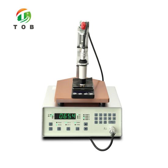
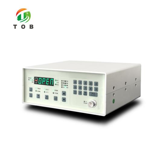
Four-Probe Electrode Coating Resistivity Tester
Brand:
TOB NEW ENERGYitem no.:
TOB-ERT-F02Border(moq):
1Payment:
L/C,T/Tproduct origin:
Chinashipping port:
XIAMEN
Four-Probe Electrode Coating Resistivity Tester for Battery Electrode Foils
Product Overview and Ideal Applications
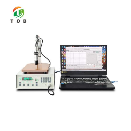
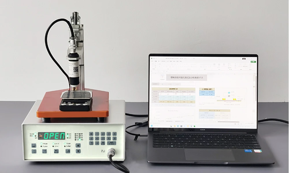
The TOB-ERT-F02B is a four-probe electrode coating resistivity tester specifically designed for measuring the resistivity and vertical sheet resistance of electrode coatings on metal foils—the composite structure found in lithium-ion battery electrodes. The instrument is supplied with a coating-resistivity/vertical-sheet-resistance probe featuring cylindrical flat-tip probes, configured with the four-probe instrument and a test platform, to measure the coating resistivity and vertical specific resistance on a metal foil.
The complete test system comprises the four-probe main unit, a pressure balance unit, and the connecting cables. The probe assembly consists of the probe pins, a probe holder, a cylindrical main body, a test-platform connecting nut, and the instrument connecting cables. The probe is fully compatible with all TOB four-probe instruments and test platforms, and is also compatible with most other manufacturers' four-probe instruments, providing flexibility for laboratories that already own other four-probe hardware.
Why this instrument exists—and why a conventional four-probe test is inadequate for battery electrodes:
The coating layer on a battery electrode foil is attached to an aluminium or copper foil that has much higher electrical conductivity than the coating itself. Because the coating is thin, its in-plane resistance is high relative to the foil. When a conventional four-probe method is used to test a battery electrode, the current distribution is dominated by the substrate: the foil acts as a nearly perfect short circuit, shunting most of the test current away from the coating. The voltage measured across the coating is therefore extremely small, and the nominal result is far lower than the true value. A conventional four-probe measurement is only valid for a material that is homogeneous, isotropic, and uniform—a condition that the electrode-coating-on-foil composite does not satisfy.
The TOB-ERT-F02B addresses this limitation by simulating the actual working state of the electrode. Using a four-terminal measurement principle, the test current flows through the path: current electrode positive → coating → copper (aluminium) foil → coating → current electrode negative. In this circuit, the resistance of the foil itself is only a few milliohms—less than 1 % of the total resistance—and can be neglected. The measured result RT = V/I therefore represents the sum of the bulk resistance of the two coating layers, from which the coating resistivity and vertical specific resistance can be calculated.
Ideal for:
- Battery electrode manufacturers and production lines that need to evaluate the conductive performance of electrode coatings on aluminium (cathode) or copper (anode) foil.
- Quality-control laboratories testing coated electrode sheets before and after calendaring to verify coating uniformity and conductivity.
- R&D groups developing new electrode formulations, where accurate coating resistivity data is needed to correlate slurry composition with electrode performance.
- Any facility that has attempted to test battery electrode coatings with a conventional four-point probe and obtained unrealistically low readings due to substrate current shunting.
Where Coating Resistivity Testing Fits in Electrode Manufacturing and Quality Control
In the production of lithium-ion battery electrodes, the electrical conductivity of the coated layer directly influences the cell's internal resistance, rate capability, and cycle life. A coating with insufficient conductivity—caused by poor dispersion of the conductive carbon, insufficient binder-to-conductor ratio, or coating defects—will exhibit an elevated resistance that limits the electrode's ability to deliver current uniformly. The TOB-ERT-F02B provides a direct, quantitative measurement of the coating's conductive performance at two key points in the production chain:
- After coating and drying (before calendaring): At this stage, the coating is porous and has not yet been compacted. Measuring the coating resistivity at this point allows early detection of formulation or coating-process problems, before the electrode advances to calendaring and cell assembly. For pressure-sensitive samples at this stage, an optional digital-display pressure test platform can be configured to monitor the applied pressure during measurement.
- After calendaring: The compacted electrode has a higher density and improved particle-to-particle contact. Comparing the resistivity before and after calendaring quantifies the effectiveness of the calendaring step and confirms that the target conductivity has been achieved.
The test platform accommodates samples with a minimum size of 4 mm × 10 mm; larger flat samples and samples of any thickness can be tested. The probe pins are arranged in a straight two-pin configuration with a spacing of 8.0 mm, and the probe pins are made of phosphor-copper alloy with nickel or gold plating, with a diameter of Φ4.0 mm. The applied pressure is adjustable between 200 g and 1000 g, with a rated pressure of approximately 500 g, adjusted through the test platform.
How the Four-Terminal Coating Resistivity Measurement Works
Why conventional four-probe testing fails for electrode coatings:
In a conventional four-probe measurement, the four probes are placed in a line on the surface, a current is passed through the outer two probes, and the voltage is measured across the inner two probes. This method assumes the test material is a homogeneous, isotropic, uniform medium. For a battery electrode, however, the structure is a thin, relatively high-resistance coating on top of a highly conductive metal foil. Because the foil is nearly an electrical short circuit, it shunts the majority of the test current. The current that actually flows through the coating is very small, and the measured voltage is correspondingly tiny. The nominal result is therefore far smaller than the true coating resistance—the conventional four-probe result is meaningless for this composite structure.
The four-terminal measurement principle of the TOB-ERT-F02B:
The TOB-ERT-F02B simulates the actual working state of the electrode by directing the test current along the electrode's natural current path. The current circuit is:
Current electrode positive → coating → copper (aluminium) foil → coating → current electrode negative
In this configuration, the test current flows through both coating layers and the foil in series. The resistance of the copper (aluminium) foil is only a few milliohms and accounts for less than 1 % of the total resistance, so it can be neglected. The measured result RT = V/I represents the sum of the bulk resistance of the two coating layers. From this value, the coating resistivity and the vertical specific resistance can be calculated using the relevant derived relationships.
Because the measurement replicates the actual current path in a working electrode, the result directly reflects the electrode's conductive performance in service, rather than a misleading surface measurement distorted by the substrate.
Technical Specifications
Measurement Range and Resolution
| Parameter | Range | Resolution |
| Resistance | 1.0 × 10⁻⁶ – 20.00 × 10³ Ω | 0.1 × 10⁻⁶ – 0.01 × 10³ Ω |
| Resistivity | 1.0 × 10⁻⁶ – 20.00 × 10³ Ω·cm | 0.1 × 10⁻⁶ – 0.01 × 10³ Ω·cm |
| Sheet Resistance | 5.0 × 10⁻⁶ – 100.0 × 10³ Ω/□ | 0.5 × 10⁻⁶ – 0.1 × 10³ Ω/□ |
Range Division and Error Grade
| Full-Scale Display | 200 | 20 | 2 | 200 | 20 | 2 | 200 | 20 |
| Test Current | 0.1 µA | 1.0 µA | 10 µA | 100 µA | 1.0 mA | 10 mA | 100 mA | 1.0 A |
| Conventional Range | kΩ·cm | kΩ·cm/□ | Ω·cm/□ | mΩ·cm/□ | ||||
| Basic Error | ± | ±1.5% FSB | ±0.5% FSB ±2 LSB | ±1.0% FSB | ||||
Test Platform Characteristics
| Parameter | Specification |
| Sample Size | Minimum 4 mm × 10 mm; large flat samples and any thickness are acceptable |
| Probe Spacing | Straight two-pin arrangement, spacing 8.0 mm |
| Probe Material | Phosphor-copper alloy with nickel/gold plating, Φ4.0 mm |
| Pressure | 200–1000 g adjustable; rated pressure approx. 500 g; adjusted through the test platform |
| Optional | Digital-display pressure test platform with pressure measurement for pressure-sensitive samples (e.g., uncalendered electrodes) |
Power Supply
| Parameter | Specification |
| Input | AC 220 V ± 10 %, 50 Hz |
| Power Consumption | < 20 W |
Dimensions and Weight
| Item | Specification |
| Main Unit Dimensions | 220 mm (L) × 245 mm (W) × 100 mm (H) |
| Net Weight | ≤ 2.5 kg |
System Composition
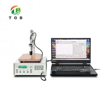
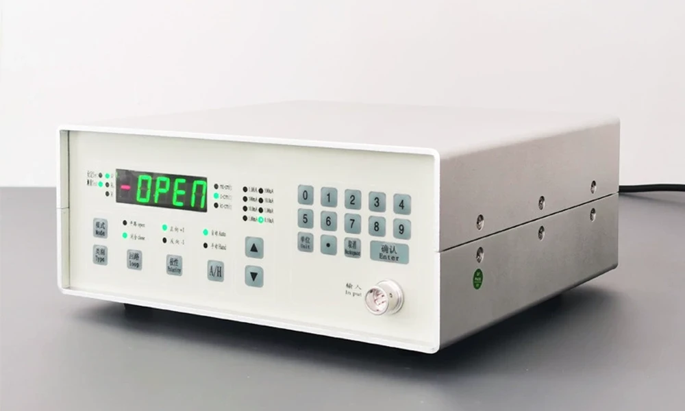
The TOB-ERT-F02B test system is composed of the following components:
| Component | Description |
| Four-Probe Main Unit | The measurement instrument that drives the probes, applies the test current, and displays the resistance/resistivity result. |
| Pressure Balance Unit | Provides the adjustable test pressure (200–1000 g) for consistent probe-to-sample contact. |
| Probe Assembly | Consists of the probe pins (phosphor-copper alloy, nickel/gold plated, Φ4.0 mm), probe holder, cylindrical main body, test-platform connecting nut, and instrument connecting cables. |
| Test Platform | Holds the electrode sample and provides the pressure adjustment mechanism. |
Compatibility: The probe is compatible with all TOB four-probe instruments and four-probe test platforms, and with most other manufacturers' four-probe instruments, allowing the probe to be used with existing equipment in the laboratory.
Common Measurement Issues and Troubleshooting
| Issue | Possible Cause | Recommended Action |
| Reading far lower than expected | The measurement is being performed in conventional four-probe surface mode rather than the four-terminal through-coating mode; or the probe is not contacting both coating layers in the correct current path. | Verify that the probe and the instrument are configured for the four-terminal coating-resistivity measurement described in the manual. Confirm that the current path passes through both coating layers and the foil. |
| Unstable or drifting readings | Probe contact pressure inconsistent; sample surface contaminated; probe tips worn. | Adjust the test-platform pressure to the rated 500 g and verify it remains constant during the measurement. Clean the sample surface and the probe tips with isopropanol. Inspect the probe tips for wear and replace if necessary. |
| Readings vary when the same sample is measured at different positions | Coating thickness or density varies across the electrode; local coating defects. | Measure at multiple positions across the electrode and record the distribution. If the variation is large, investigate the coating process for uniformity issues. |
| High contact resistance indicated | Oxidized or contaminated probe tips; insufficient pressure. | Clean or polish the probe tips. Increase the pressure within the 200–1000 g range. |
| Pressure-sensitive sample (uncalendered electrode) shows inconsistent results | Applied pressure deforms the porous coating, changing the measured resistance. | Use the optional digital-display pressure test platform to monitor and control the pressure precisely. Compare measurements at a consistent pressure setting. |
Recommended Measurement Practice for Battery Electrode Coatings
- Sample preparation: Cut a flat test piece from the coated electrode with a minimum size of 4 mm × 10 mm. For production-quality testing, take samples from multiple positions across the electrode width (e.g., left, center, right) to assess coating uniformity.
- Surface cleanliness: Wipe the sample surface with a lint-free cloth and isopropanol to remove contamination before measurement. Oil or debris on the coating surface will add contact resistance.
- Pressure setting: For calendered electrodes, use the rated pressure of approximately 500 g. For uncalendered (pressure-sensitive) electrodes, use the optional pressure-test platform and record the exact applied pressure so that measurements are comparable.
- Measurement sequence: Record the resistance, resistivity, and sheet-resistance values as appropriate for your quality protocol. For monitoring the effect of calendaring, measure the same formulation before and after calendaring and compare the resistivity values.
- Calibration: Verify the instrument against a known standard resistor periodically (per the instrument's calibration schedule) to ensure the accuracy specification is maintained.
Engineering FAQ
Q1: Why can't I use a conventional four-point probe to test my electrode coating?
A conventional four-point probe assumes the test material is a homogeneous, isotropic, uniform medium. A battery electrode is a composite of a thin, relatively high-resistance coating on a highly conductive aluminium or copper foil. The foil acts as a near-perfect short circuit and shunts most of the test current, so the measured voltage is extremely small and the nominal result is far below the true coating resistance. The TOB-ERT-F02B solves this by using a four-terminal measurement that directs the current along the electrode's actual working path, so the foil's negligible resistance (less than 1 % of the total) does not distort the result.
Q2: What is the difference between the "four-probe" and "four-terminal" terminology here?
In this instrument, "four-probe" refers to the probe hardware (the cylindrical probe with its pin configuration), while "four-terminal" refers to the measurement principle—separate current and voltage terminals—which is the appropriate method for the coating-on-foil composite. The probe assembly is a four-probe device, but it is applied using a four-terminal current-path configuration to obtain the coating resistivity, rather than the conventional in-plane four-point measurement.
Q3: What is the minimum sample size I can test?
The minimum sample size is 4 mm × 10 mm. Larger flat samples and samples of any thickness can also be tested, with no upper limit on the flat dimension.
Q4: Can I use this probe with my existing four-probe instrument from another manufacturer?
Yes. The specification states that the probe is compatible with all TOB four-probe instruments and test platforms, and is also compatible with most other manufacturers' four-probe instruments. If you have a specific instrument model, contact TOB to confirm compatibility.
Q5: How does the measured result relate to the actual electrode performance?
The measured result RT = V/I represents the sum of the bulk resistance of the two coating layers in the current path, which simulates the actual working state of the electrode. This value directly reflects the coating's conductive performance in service. Lower coating resistivity indicates better electron transport through the electrode, which contributes to lower cell internal resistance and improved rate capability.
Ready to measure the true conductive performance of your electrode coatings without the distortion caused by substrate current shunting? Request a quotation for the TOB-ERT-F02B, or contact our testing-instrument engineers to discuss the optional pressure-test platform for uncalendered electrodes and compatibility with your existing probe hardware.
tob.amy@tobmachine.com | +86 181 2071 5609
You May Also Need
1. Four-Terminal Resistivity Tester for Lithium-Ion Battery Powder Materials — A four-terminal resistivity tester for measuring the resistivity of battery powder materials under applied pressure. Complements the TOB-ERT-F02B by providing powder-level conductivity measurement for active materials and conductive additives before electrode fabrication.
2. Conductivity Meter — A general-purpose instrument for measuring the ionic conductivity of liquid electrolytes and solid electrolyte materials. Pairs with the TOB-ERT-F02B for a comprehensive evaluation of both electrode electronic conductivity and electrolyte ionic conductivity.
3. Automatic Lithium Battery Electrode Sheet Resistance Tester — An automatic electrode sheet resistance tester for higher-throughput, production-line electrode resistance measurement. Complements the TOB-ERT-F02B when automated, high-volume testing is required.
Previous:
Cylindrical Mandrel Bend Tester for Battery Electrode Flexibility TestNext:
Tensile Strength Testing Machine
If you are interested in our products and want to know more details,please leave a message here,we will reply you as soon as we can.



 subscribe to us