Chinese
 français
 Deutsch
 italiano
 español
 português
 Nederlands
 日本語
日本語 한국의
한국의




Categories
Hot Products
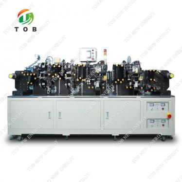
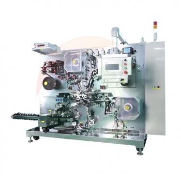
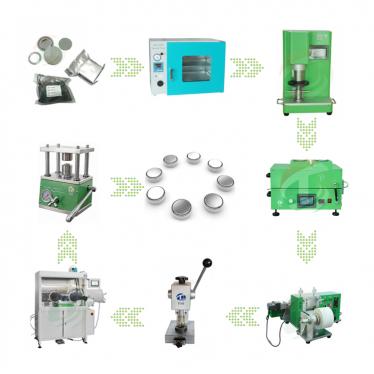
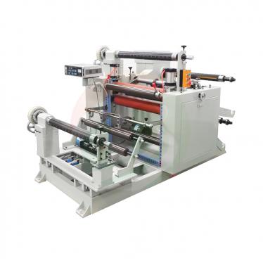
Patent CN215451488U - 3-Axis Electrolyte Filling & Sealing
Sep 24,2026A position sensor locates the battery and three motor-driven lead-screw axes move the injection pipe to fill and seal it in three directions - no manual feeding, no hand stamping.
Full specification and drawings: CN215451488U on Google Patents
Sealing is one of the last operations a lithium battery goes through, and in the prior art it was performed the slow way: an operator fed each cell into a press by hand and a stamping action closed it. The specification of CN215451488U calls the sealing step an important link in lithium battery production and identifies the manual feeding-and-stamping route as the bottleneck - sealing efficiency was low.
The patent answers with a machine that does the positioning itself. A sensor detects the cell on a working plate, and three electric motors drive three lead screws to move an injection pipe over the cell and fill and seal it. The whole handling cycle - position, inject, seal - no longer depends on an operator's hands.
Patent Information
| Publication number | CN215451488U |
| Application number | CN202122096808.2U |
| Title (original) | 一种电池生产用封口装置 (3-Axis Electrolyte Filling & Sealing Machine) |
| Inventors | Huang Zhengyao (Dany Huang); Chen Lucai (Tobey Chen) |
| Current assignee | XIAMEN TOB NEW ENERGY TECHNOLOGY Co., Ltd. - the registered entity of TOB NEW ENERGY |
| Filing date | 1 September 2021 |
| Grant date | 7 January 2022 |
| Document type | Utility model (kind code U) |
| Legal status | Active |
| Anticipated expiration | 1 September 2031 |
| Drawings | 7 figures |
| Official record | CN215451488U on Google Patents |
The Production Problem This Patent Solves
Manual sealing is slow and labour-bound. In the existing process the battery is fed by hand and sealed by a stamping action. Each cell needs to be aligned with the sealing station individually, and the operator is part of every cycle. For a step positioned at the very end of a lithium battery line, that manual rhythm sets the ceiling for the whole line's output.
Filling and sealing call for accuracy in three dimensions. To inject and seal a cell the injection pipe must arrive above the cell opening from the right direction, at the right height. A rigid single-station tool cannot be adjusted quickly when the cell type or the station layout changes.
The utility model addresses both points: it senses where the cell is, then drives the injection pipe along three orthogonal axes so the filling and sealing head can be positioned without any manual alignment.
How the Mechanism Works
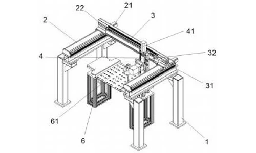
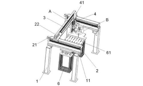
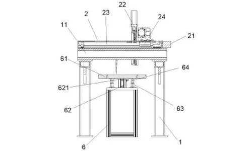
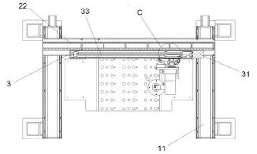
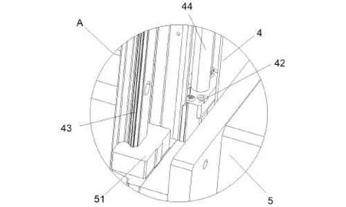
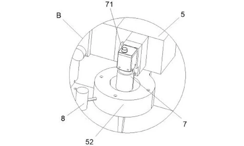
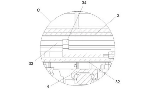
The machine builds three linear axes out of three electric motors and three lead screws, stacked on successive cross beams above a working plate. Figures 1-4 show the overall machine in two perspective views and two cross-section views; Figures 5-7 give the enlarged details called out at A, B and C.
Three stacked motor-and-lead-screw axes
A frame carries a first connecting plate on each side at its upper end, and a first cross beam spans the two plates. The first motor at the rear of the first cross beam turns the first lead screw, and the meshing first connecting block rides on it, carrying the second cross beam in the front-rear direction. The second motor at the right end of the second cross beam turns the second lead screw and moves the third cross beam in the left-right direction. The third motor on top of the third cross beam turns the third lead screw, and its connecting block moves the connecting frame in the up-down direction. All three motors are electrically connected to an external power supply and an external controller.
Filling head with position sensor
The connecting frame carries the injection pipe at its front end. The pipe has an injection port at its upper end (where the sealing-liquid tube connects) and a limiting ring on its outer end, seated at the lower-left of the connecting frame. A position sensor is mounted behind the limiting ring. When a battery is placed in the clamping hole of the working plate, the sensor recognises the cell and sends a signal to the controller - that signal starts the positioning sequence.
Work plate with electric-cylinder lift
A support frame stands below the injection pipe, and the working plate sits on top of it. An electric cylinder on the support frame drives a telescopic rod whose upper end is attached to the underside of the working plate, so the plate can be raised and lowered for loading and unloading. A connecting pipe on the underside of the plate houses a spring rod whose lower end rests on the support frame; the spring rod is in interference fit with the connecting pipe, so the plate moves up and down smoothly instead of tilting.
Guided carriage and frame stiffening
The connecting frame also carries a slide block at the rear-left that runs on a slide rail mounted on the third cross beam, keeping the up-down carriage stable. Below, the frame is bolted to the first connecting plates and stiffened by a triangular plate in each corner angle.
Working sequence as published: the operator connects the injection port to the sealing-liquid tube and powers the machine; a battery is placed in the clamping hole; the position sensor identifies the cell and signals the controller; the controller runs the first motor (front-rear), the second motor (left-right) and the third motor (up-down) in turn so the connecting frame positions the injection pipe and fills and seals the cell; when the plate must be loaded, unloaded, or the pipe must inject vertically, the controller starts the electric cylinder and the telescopic rod moves the working plate.
Claimed Benefits
| Benefit | Mechanism responsible |
|---|---|
| Higher sealing efficiency | Position sensor locates the battery, then the injection pipe is driven in three directions to fill and seal without manual alignment |
| Higher practicality | Electric cylinder raises and lowers the working plate for loading/unloading and for two-way vertical injection |
| Stable plate travel | Spring rod in interference fit with the connecting pipe, plus slide block and slide rail on the third cross beam |
How It Compares with Manual Feed-and-Stamp Sealing
In the existing process the battery was fed by hand and sealed by a stamping action, with the operator part of every cycle. This patent replaces that rhythm with motor-driven positioning and actuation.
| Dimension | Conventional approach | This patent design |
|---|---|---|
| Cell locating | Operator aligns every cell with the sealing station | Position sensor locates the battery automatically |
| Filling and sealing | Manual stamping by the operator | Three motor-and-lead-screw axes drive the injection pipe in three directions |
| Loading | Fixed work plate, awkward access | Electric cylinder raises and lowers the work plate for loading and unloading |
Where This Technology Is Used Today
CN215451488U covers the positioning-and-filling architecture used in TOB's battery sealing and electrolyte filling equipment: sense the cell, move the head in three axes, fill and seal. That is exactly the sequence a production sealing station must repeat reliably on every cell.
Related equipment enquiries: request a quote
Frequently Asked Questions
What does patent CN215451488U cover?
It covers a battery sealing machine for battery production in which three electric motors drive three lead screws on stacked cross beams, moving a connecting frame and its injection pipe in the front-rear, left-right and up-down directions. A position sensor locates the battery in a clamping hole on a working plate, and the controller then drives the injection pipe to fill and seal the cell.
Why is manual sealing a problem in battery production?
The specification states that the prior art sealed batteries by manual feeding and stamping, and that this made sealing efficiency low. Because sealing is an important step in lithium battery production, that manual rhythm limits the output of the whole line.
How does the machine know where to inject the sealing liquid?
A position sensor behind the limiting ring of the injection pipe recognises the battery placed in the clamping hole of the working plate and sends a signal to the controller. The controller then starts the three motors in sequence so the injection pipe reaches the correct position in three directions before filling and sealing.
What does the electric cylinder under the work plate do?
It drives a telescopic rod attached to the underside of the working plate, raising and lowering the plate for loading and unloading, and enabling two-way vertical injection. A spring rod in interference fit with a connecting pipe keeps the plate movement stable.
Who owns patent CN215451488U?
TOB NEW ENERGY holds this granted utility model. It is filed under the company's registered Chinese entity and was co-invented by Huang Zhengyao (Dany Huang) and Chen Lucai (Tobey Chen).
Is patent CN215451488U still in force?
Yes. It is Active, filed on 1 September 2021 with anticipated expiration on 1 September 2031.
Full specification and drawings: CN215451488U on Google Patents
 subscribe to us