Chinese
 français
 Deutsch
 italiano
 español
 português
 Nederlands
 日本語
日本語 한국의
한국의




- Home
- >
Battery Tester
- >
Battery and Supercapacitor Safety Tester
- >
Temperature Cycling Test Chamber
Categories
Hot Products
Loading...
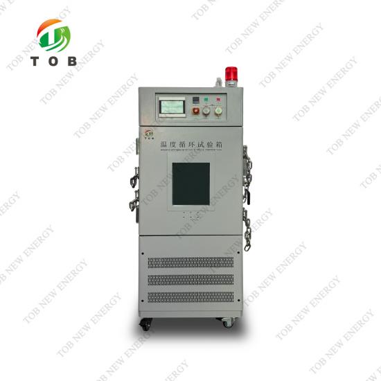
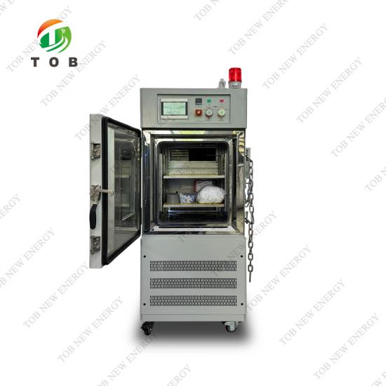
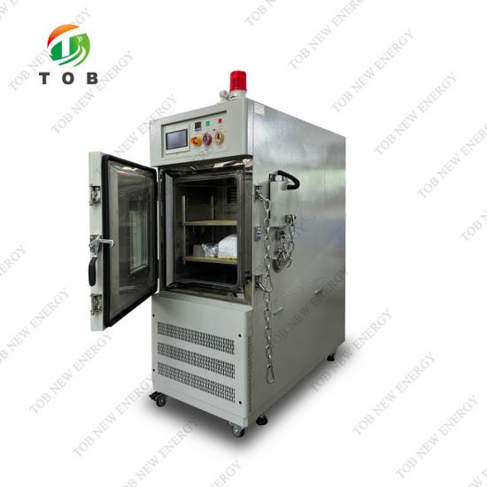
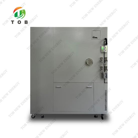
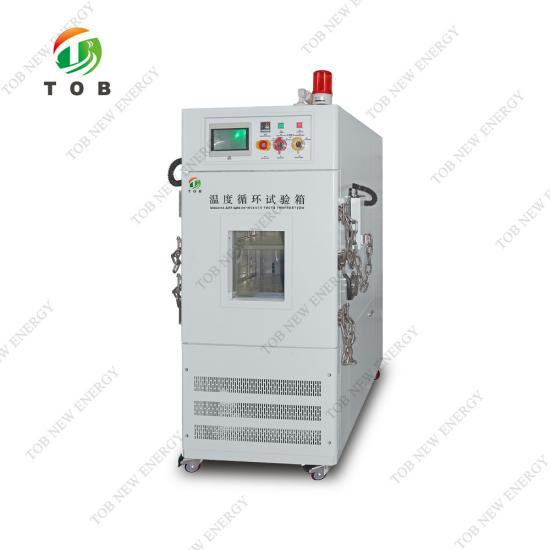
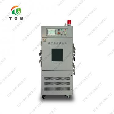
Temperature Cycling Test Chamber
Brand:
TOB NEW ENERGYitem no.:
TOB-KS5-150Corder(moq):
1Payment:
L/C, T/Tproduct origin:
Chinashipping port:
XIAMEN
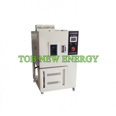
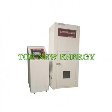
Temperature Cycling Test Chamber for Battery Cells | TOB-KS5-150C
Product Overview and Ideal Applications
A temperature cycling test chamber subjects products to repeated, controlled transitions between extreme hot and cold temperatures to uncover latent design weaknesses, material fatigue, and manufacturing defects that would not appear under steady‑state conditions. For lithium‑ion battery cells, temperature cycling is not merely a quality‑assurance exercise—it is a regulatory requirement under IEC 62133, UL 1642, and UN 38.3, and a key predictor of field reliability in electric vehicles and energy storage systems subjected to daily thermal swings.
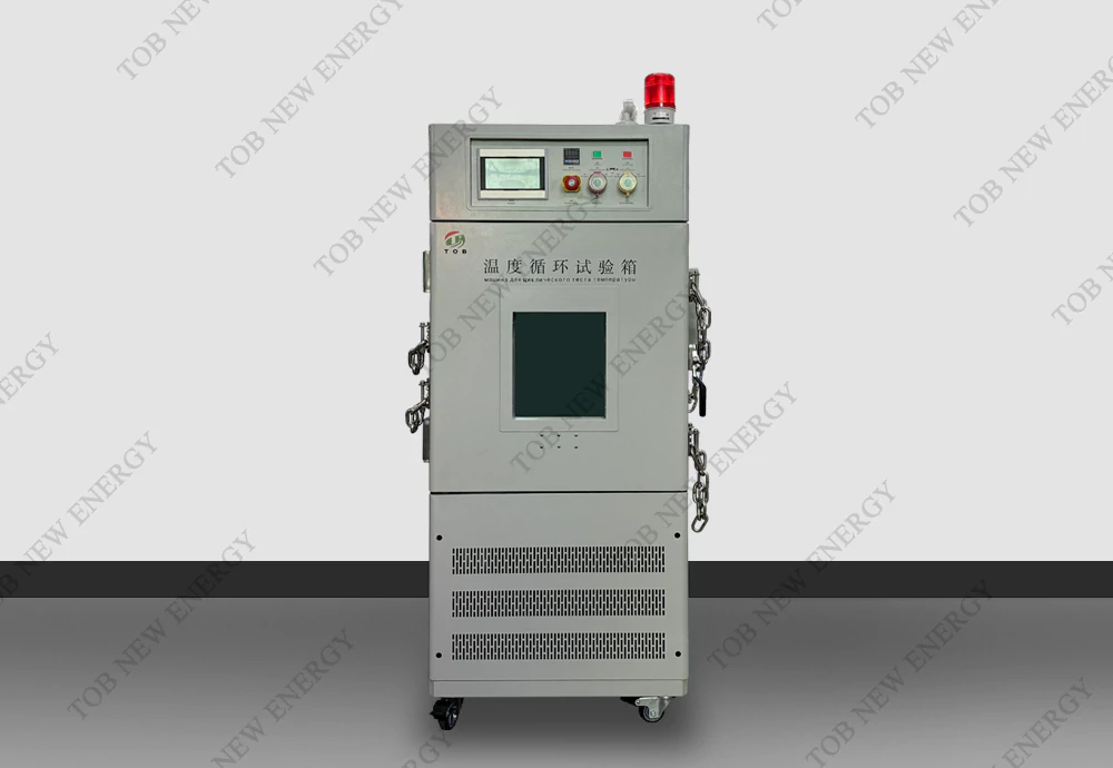
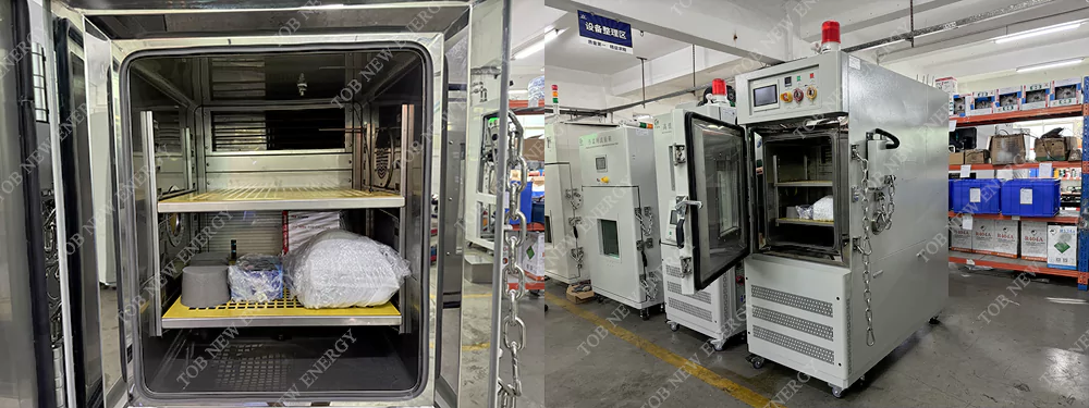
The TOB‑KS5‑150C is a 150‑litre, high‑performance temperature cycling chamber purpose‑built for single‑cell and small‑component testing. It spans a temperature range of –40 °C to +150 °C with a heating and cooling rate of approximately 5 °C/min across the full range (non‑linear average, no load), enabling the rapid transitions demanded by accelerated‑life test protocols. The chamber is constructed with a reinforced 2 mm‑thick SUS 304 stainless‑steel interior base, a 100 mm polyurethane‑insulated wall, and battery‑specific safety features including explosion‑proof chains, a pressure‑relief door, and a smoke‑exhaust vent. A tri‑colour alarm light indicates running status at a glance, while the PT100 wet‑dry bulb sensor provides temperature readings with ±0.5 °C fluctuation and ≤±2 °C gradient uniformity.
Ideal for:
- Battery cell manufacturers performing mandatory temperature cycling tests as per IEC 62133‑2012 §7.2.4, UL 1642 §18, and UN 38.3 T.2 on lithium‑ion cylindrical, pouch, and prismatic cells.
- R&D teams evaluating new electrode materials and electrolyte formulations under thermal stress to identify failure modes such as SEI degradation, electrolyte freezing, and current‑collector corrosion.
- Quality‑control laboratories verifying batch‑to‑batch consistency of production cells by subjecting random samples to a standard thermal cycle and measuring capacity retention and impedance growth.
- Electronics and component manufacturers requiring rapid temperature change testing per IEC 60068‑2‑1 (Cold) and IEC 60068‑2‑2 (Dry Heat) for automotive, aerospace, and industrial applications.
Where Temperature Cycling Fits in Battery Cell Qualification
Temperature cycling is an environmental stress test applied after cell assembly and formation, and before shipment or pack integration. The test protocol for a lithium‑ion cell typically follows this sequence:
- Initial characterisation: The cell's capacity, internal resistance, and open‑circuit voltage are measured at room temperature.
- Temperature cycling (the TOB‑KS5‑150C's role): The cell is subjected to a predetermined number of cycles between a low‑temperature extreme (e.g., –40 °C) and a high‑temperature extreme (e.g., +70 °C or +85 °C), with defined ramp rates and dwell times at each extreme. The test may be performed with the cell in a charged or discharged state, depending on the applicable standard.
- Post‑test evaluation: After the cycling is complete, the cell is visually inspected for leakage, deformation, or rupture. Its capacity and impedance are measured again and compared to the pre‑test values. The cell may also be subjected to a final charge‑discharge cycle to verify functionality.
- Pass/fail determination: The cell must retain a specified percentage of its initial capacity, show no signs of physical damage, and remain functional.
The TOB‑KS5‑150C's 5 °C/min ramp rate is particularly significant. Many older or lower‑cost cycling chambers manage only 1–2 °C/min, which lengthens the total test time and, more importantly, fails to represent the rapid thermal transients that a cell may experience in real‑world scenarios—for example, an EV battery being fast‑charged in a cold winter environment after a highway drive, or a portable electronics battery moving from an air‑conditioned office to a hot car interior within minutes. The faster ramp rate of the TOB‑KS5‑150C provides a more aggressive and representative stress, capable of revealing defects that a slower chamber would miss.
Battery‑specific safety integration:
Because lithium‑ion cells can vent or enter thermal runaway if a latent defect is triggered by thermal stress, the TOB‑KS5‑150C is equipped with safety mechanisms that go well beyond those of a standard environmental chamber:
- Explosion‑proof chains (2 pcs): Secure the chamber door to the frame, preventing it from being blown open during a cell failure.
- Smoke exhaust vent (1 pc): Passively vents smoke and gases out of the chamber, reducing internal pressure and preventing the accumulation of flammable electrolyte vapours.
- Explosion‑proof pressure relief door (1 set): Opens at a pre‑set internal pressure to safely release energy in the event of a thermal runaway.
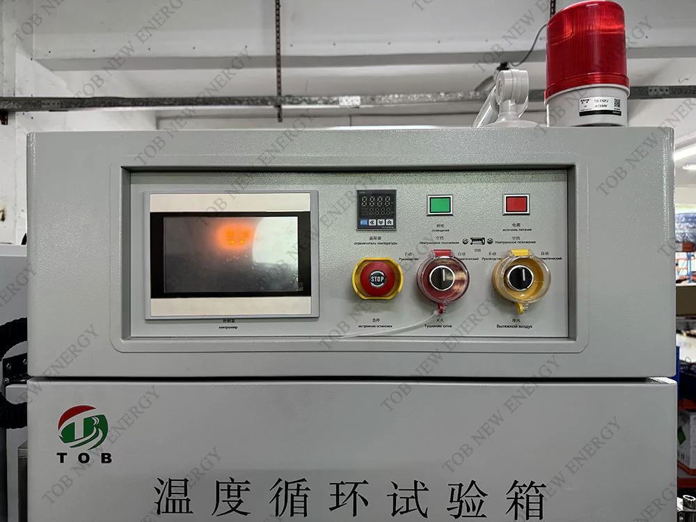
- Tri‑colour light alarm: Green for normal running, yellow for a pending or minor alarm, red for a fault or safety event—allowing laboratory personnel to monitor the chamber from a distance.
These features enable the TOB‑KS5‑150C to be placed directly on a production or R&D laboratory floor without requiring a separate blast‑proof enclosure.
How the Rapid Temperature Cycling Chamber Works
The TOB‑KS5‑150C achieves its high ramp rate through a combination of a powerful compressor, an efficient finned‑type evaporator, and a forced‑air circulation system. The chamber follows a "top‑to‑bottom" air supply design: conditioned air is injected from the upper plenum, flows uniformly over and around the test specimens, and is drawn back into the treatment section from the bottom, ensuring a consistent temperature gradient of ≤±2 °C throughout the entire 150‑litre working volume.
Heating and cooling system
- Heating: A naked‑wire nickel‑chromium alloy heating tube, positioned in the air stream, provides rapid and efficient heating. The power delivery is modulated by a solid‑state relay under PID control from the main temperature controller, which reads the chamber temperature via a PT100 wet‑dry bulb sensor. The heating rate of 5 °C/min is achieved with a power rating of 9 kW (three‑phase 380 V), significantly higher than that of a standard steady‑state chamber, ensuring that the thermal mass of even multiple cells does not overly slow the ramp.
- Cooling: A Germany‑sourced GEA Boke (or equivalent) air‑cooled compressor circulates R448A refrigerant through a high‑efficiency, multi‑segment finned‑type evaporator located directly in the air‑handling plenum. The compressor operates in a modulating mode: during the cooling ramp, it runs at full capacity; during the dwell phases, it cycles or unloads to maintain the set temperature with minimal overshoot. A finned‑type air‑cooled condenser, also force‑convection‑cooled, rejects the heat to the ambient environment.
Air circulation and temperature uniformity
- A Taiwan‑brand low‑pressure asynchronous motor drives a multi‑blade centrifugal blower with high/low‑temperature‑resistant aluminium blades. The air is directed through a carefully designed duct system to create a uniform velocity profile across the entire specimen zone. The PT100 temperature sensor is positioned at the return‑air point, where the air temperature is most representative of the average chamber condition. The controller uses its PID algorithm to maintain the set temperature with a fluctuation of ±0.5 °C and a gradient across the workspace of ≤±2 °C.
Control and monitoring
- The chamber is managed by a dedicated temperature controller that offers an RS‑485 or LAN communication port (one must be selected during ordering). The controller supports:
- Programmable temperature cycling profiles with up to 255 segments, enabling the creation of complex multi‑step cycles with different ramp rates and dwell times.
- Real‑time trend display on the built‑in screen (if equipped) or via the connected PC software.
- Independent over‑temperature protection via a separate, adjustable temperature protector that operates on a different sensor circuit, providing a fail‑safe mechanism should the main controller malfunction.
Chamber construction and insulation
- External: Cold‑rolled steel with a durable painted finish, providing a clean, corrosion‑resistant exterior that is easy to wipe down.
- Internal: 1.0 mm SUS 304 stainless‑steel walls and ceiling, with a reinforced 2.0 mm‑thick SUS 304 base. The thicker base is essential for supporting the weight of multiple battery cells and their fixtures without deformation. This is a notable design upgrade compared to many chambers that use the same thin gauge on the floor, leading to dents and compromised insulation over time.
- Insulation: 100 mm of polyurethane (PU) foam surrounds the workspace. This thickness, combined with the superior insulating properties of PU, keeps the external surface temperature low (the outer shell remains at a safe temperature even when the interior is at +150 °C) and minimises heat exchange with the ambient, reducing energy consumption.
Key Engineering Advantages of the TOB‑KS5‑150C
Rapid 5 °C/min Ramp Rate Across Full Temperature Range
The average heating and cooling rate of 5 °C/min (–40 °C to +85 °C and back, no load) enables the execution of IEC 62133 and UL 1642 temperature cycling tests in a fraction of the time that a 1–2 °C/min chamber would require. For a typical 10‑cycle test, this can reduce the total test duration by several hours, increasing laboratory throughput. The ramp rate is non‑linear but achieves the average speed necessary for regulatory compliance.
Battery‑Specific Safety Package
The explosion‑proof chains, smoke exhaust vent, and explosion‑proof pressure‑relief door are integrated directly into the chamber design. These three features work together: the chains hold the door shut during a cell venting event, the smoke vent passively exhausts hot gases, and the pressure‑relief door opens if the internal pressure exceeds a safe limit, preventing catastrophic chamber rupture. The tri‑colour alarm light provides immediate visual indication of the chamber's status from across the laboratory.
Reinforced 2 mm SUS 304 Base — Built for Heavy Cell Fixtures
Most environmental chambers of this size use 1.0 mm or thinner stainless steel for the entire interior, including the floor. The TOB‑KS5‑150C uses a 2 mm‑thick SUS 304 base, specifically to support the weight and point loads of dense battery cell fixtures without denting or warping. This prevents deterioration of the insulation under the floor and maintains a perfect seal around the door gasket over years of service.
Large 150 L Capacity with Efficient Air Distribution
The working volume of 150 L (W500 × H600 × D500 mm) can accommodate multiple pouch cells, several cylindrical cells in holders, or entire small electronic assemblies. Two insulated sample shelves, each rated for 30 kg, provide ample load capacity. The top‑to‑bottom forced‑air circulation and the multi‑blade centrifugal blower ensure that all specimens, regardless of shelf position, experience the same temperature profile within the ±2 °C uniformity specification.
Operates Under Standard Laboratory Conditions
The air‑cooled design means no external cooling water is required. The chamber operates in ambient temperatures from +5 °C to +35 °C and up to 85 % relative humidity, conditions easily met in a typical air‑conditioned laboratory. The three‑phase 380 V power supply at 9 kW can be accommodated by most industrial and academic electrical panels.
Compliant with International and National Test Standards
The chamber is verified to meet IEC 62133‑2012 §7.2.4 (Temperature cycling), UL 1642 §18 (Temperature cycling test), UN 38.3 T.2 (Thermal test), IEC 60068‑2‑1 (Cold), and IEC 60068‑2‑2 (Dry Heat). Testing laboratories can thus use it to certify cells and products to these standards without performing a separate chamber‑qualification study.
Technical Specifications
|
1.Product Name |
|||
|
1.1 Name 1.2 Model |
Temperature Cycling Test Chamber TOB-KS5-150C |
||
|
2. Application & Limitation |
|||
|
2.1 Application |
Mainly used for Single cell and electronic products,components high low temperature test,temperature change etc. Environment simulate reliability test. |
||
|
3. Volume & Dimension |
|||
|
3.1 Effective Volume |
150 L |
||
|
3.2 Inner Dimension |
W 500 mm*H 600 mm*D 500 mm |
||
|
3.3 Overall Dimension |
W 750 mm*H 1780 mm*D 1500 mm Kindly remark:exact overall dimension pls refer to the final design drawing ! |
||
|
4. Performance |
|||
|
4.1 Condition |
Air cooling type under environment temp.+5℃~+35℃,relative humidity≤85%。No load(without specimen in the testing zone) |
||
|
4.2 Temp. Range |
-40℃~+150℃ |
||
|
4.3 Temp. Fluctuation |
±0.5℃ |
||
|
4.4 Temp. Deviation |
|||
|
4.5 Temp. Gradient |
≤±2.0℃ |
||
|
4.6 Temp. Heating Time |
From -40℃to 85℃,full range non-linear average about 5℃/mins,no load |
||
|
4.7 Temp. Cooling Time |
From 85℃to -40℃,full range non-linear average about 5℃/mins,no load |
||
|
4.8 Temp. Overshoot |
≤±2℃ |
||
|
4.9 Noise |
≤70 dB(A Level) |
||
|
4.10 Weight |
Approx 600 Kg |
||
|
4.11 Power |
380 V, 50 Hz,Three phase, 9 Kw |
||
|
4.12 Standard Compliance |
IEC62133-2012-Chapter 7.2.4 Temperature cycling UL1642-Chapter 18 Temperature cycling test UN38.3 Test T.2:Thermal test IEC60068-2-1:2007 Environmental testing - Part 2: Test methods - Tests A: Cold IEC60068-2-2:2007 Environmental testing for electric and electronic products Test methods - Tests B:Dry Heat |
||
|
5. Structure & Material |
|||
|
5.1 External Chamber |
Cold-roll steel with painting. |
|
|
|
5.2 Internal Chamber |
1.0 mm SUS#304 stainless steel. Bottom: 2 mm thick #304 stainless steel, |
|
|
|
5.3 Insulation Material |
100 mm PU Polyurethane foam insulation material |
|
|
|
5.4 Chamber Door |
Single open door |
|
|
|
5.5 Observation Window |
Vacuum glass observation window (Size refer design drawing) |
|
|
|
5.6 Testing Hole |
2 Pcs of¢400 mm testing hole on side of the chamber, with silicon seal and stainless steel cover. |
|
|
|
5.7 Sealing |
Adopt original imported silicon rubber strip, with high sealing performance. |
|
|
|
5.8 Sample Holder |
Sample holder with insulation material,2 layers, capacity less than 30Kg/layer. |
|
|
|
5.9 Lighting inside chamber |
1 set of energy saving light inside the observation window |
|
|
|
5.10 Tri-color light alarm system |
1 set of Tri-color light alarm to indicated the running status |
|
|
|
5.11 Safety Functions |
1 piece smoke exhaust vent. 2 pieces of Explosion proof chain on the chamber’s side. 1 set of explosion-proof pressure relief door. |
|
|
|
6. Air Supply System |
|
||
|
6.1 Air supply |
|
||
|
6.2 Cyclic Motor |
Taiwan brand low pressure asynchronous motor |
|
|
|
6.3 Blower |
Multi-blades centrifugal circulating blower, high low temp. resistant aluminum blades |
|
|
|
6.4 Sensor |
PT100 temperature sensor(Wet-dry bulb) |
|
|
|
7. Refrigeration System |
|
||
|
Air cooling method |
Air cooling type compressor |
|
|
|
7.1 Compressor |
Germany GEA Boke or similar level compressor |
|
|
|
7.2 Refrigerant |
R448a |
|
|
|
7.3 Condenser |
Air cooling high efficiency forced convection finned type |
|
|
|
7.4 Evaporator |
High efficiency multi-segment fin type evaporator |
|
|
|
Oil Separator,etc... |
|
||
|
8. Heating System |
|
||
|
8.1 Heating Tube |
Naked wire type nickel chromium alloy electric heating tube |
|
|
|
9. Controller & Control Circuit- controller |
|
||
|
9.1 Controller |
RS-485 or Lan port only can be choose one of them. |
|
|
|
10.1 Protection Function |
|
||
|
|
1. With specimen anti-condensing, over-temperature protection (also with independent adjustable temperature protector) 2. No fuse protection switch 3. Heater over-temp. Protection switch 4. Compressor over-load, over heating 5. Compressor high low pressure protection 6. System over current protection device |
|
|
|
11. Other Accessories |
|
||
|
11.1 Standard Configuration |
1. 2 layers insulation sample shelf ,loading capacity (average)30 Kg/Layer. 2. 2 Corks for diameter 50 mm testing hole. 3. Operation & Maintenance manual and monitoring software |
|
|
|
12. Operating Condition |
|
||
|
|
1. Environment Temp. : 5℃-35℃; 2. Relative Humidity: ≤85%RH; 3. Atmospheric Pressure: 80 kPa~106 kPa 4. Away from strong vibration source 5. Power source: 380 V AC(±10%),50 Hz 3 Phase 4 wires+grounding wire, earthing resistance≤4Ω |
|
|
Why Choose TOB‑KS5‑150C Over a Standard Steady‑State Environmental Chamber
| Feature | TOB‑KS5‑150C | Typical Steady‑State Chamber (similar volume) |
| Ramp rate | ≈ 5 °C/min (heating and cooling) | Often 1–3 °C/min |
| Temperature range | –40 °C to +150 °C | Often –20 °C to +100 °C, or –40 °C to +150 °C but with slower ramps |
| Interior base thickness | 2 mm SUS 304 (reinforced) | Typically 1.0 mm, prone to dents under heavy loads |
| Battery safety features | Explosion‑proof chains, pressure‑relief door, smoke vent, tri‑colour alarm | Usually none beyond an over‑temp cut‑off |
| Heating/cooling power | 9 kW, three‑phase, German compressor | Often 4–6 kW, slower response |
| Insulation thickness | 100 mm PU foam | Often 75–80 mm |
| Controller communication | RS‑485 or LAN (industrial protocol) | Often RS‑232 only |
| Loading capacity per shelf | 30 kg per shelf, 2 shelves | Often 15–20 kg per shelf |
| Standard compliance | IEC 62133, UL 1642, UN 38.3, IEC 60068‑2‑1/2 | May require additional qualification |
Why battery testing labs invest in a rapid‑cycling chamber:
The key metric is not the steady‑state temperature accuracy—most environmental chambers can hold a setpoint within ±1 °C. The metric that matters for temperature cycling is the ramp rate, because it directly governs the total test time and the aggressiveness of the thermal stress. A 5 °C/min chamber can complete a UL 1642 10‑cycle test in roughly the same wall‑clock time that a 2 °C/min chamber requires for 4 cycles. For a busy testing laboratory, this throughput difference translates directly into revenue and customer responsiveness.
Engineering FAQ — Temperature Cycling for Battery Cells
Q1: How do I determine whether a 5 °C/min ramp rate is appropriate for my specific test standard?
The test standard typically defines the maximum allowable transition time between the hot and cold extremes, not the specific ramp rate. For example, UN 38.3 T.2 specifies a maximum transition time of 30 minutes between –40 °C and +75 °C. The TOB‑KS5‑150C, with a ramp rate of 5 °C/min, completes this transition in approximately 23 minutes ((75 − (–40)) / 5 = 23 min), which is within the 30‑minute requirement. If your standard requires an even faster transition, you may need to reduce the specimen mass or consider a chamber with a higher ramp rate. For standards that do not specify a limit, 5 °C/min is a practical industrial rate that balances test acceleration with chamber cost and energy consumption.
Q2: What is the maximum heat load (specimen mass and power dissipation) that this chamber can handle while still maintaining the 5 °C/min ramp rate?
The 5 °C/min ramp rate is specified under no‑load conditions. When an actual specimen is placed in the chamber, the ramp rate will be slower because the specimen's thermal mass must also be heated or cooled. As a guideline, a specimen with a total thermal mass of 50 kg of steel equivalent will reduce the ramp rate to approximately 3–4 °C/min. For accurate cycle‑time estimates, provide TOB with your specimen's material, mass, and dimensions, and our thermal engineers can calculate the expected ramp rate under load.
Q3: Is the chamber suitable for testing cells that are actively being charged and discharged during temperature cycling?
Yes, the two φ400 mm testing ports are specifically sized to allow battery‑cycler cables to pass through while maintaining the chamber's thermal seal. The large diameter also accommodates multiple cables if several cells are tested simultaneously. For active cycling during temperature exposure, ensure that the cycler cables are rated for the full temperature range (–40 °C to +150 °C) and that the cable glands on the testing ports are properly tightened to prevent moisture ingress during cold‑to‑hot transitions.
Q4: How is the pressure‑relief door designed to operate, and does it require resetting after activation?
The explosion‑proof pressure‑relief door is a spring‑loaded or burst‑disc mechanism that opens at a pre‑set internal pressure, typically a few hundred pascals above ambient. If it activates due to a cell venting or thermal runaway event, the door must be inspected and re‑set or replaced before the chamber is returned to service. The exact re‑setting procedure depends on the mechanism type and is described in the maintenance manual. The door is designed to protect the chamber structure and the laboratory personnel from the effects of a sudden internal over‑pressure, and its activation is a rare but critical safety function.
Q5: What maintenance is required for the German compressor?
The GEA Boke compressor is a hermetic or semi‑hermetic unit that requires minimal routine maintenance. The air‑cooled condenser fins should be cleaned with compressed air every three months (or more frequently in dusty environments) to maintain heat‑rejection efficiency. The refrigerant charge (R448A) is sealed for life; if a leak is suspected, a service technician should pressure‑test the system and locate the leak before recharging. The oil separator helps return lubricating oil to the compressor crankcase; its filter element should be replaced according to the maintenance schedule in the manual. The compressor's over‑load and over‑heating protections will shut it down before damage occurs if operating conditions exceed safe limits.
Ready to subject your cells to the rapid thermal cycling required by IEC 62133, UL 1642, and UN 38.3? Request a quotation for the TOB‑KS5‑150C. Include your specimen mass, dimensions, and the test standard you must comply with, and our thermal engineers will provide a cycle‑time calculation and a recommended test configuration.
tob.amy@tobmachine.com | +86 181 2071 5609
You May Also Need
- Battery Materials — High‑purity cathode and anode active materials, solid electrolytes, and current collector foils whose thermal stability can be verified with temperature cycling tests.
- TOB‑TH‑80C Temperature Humidity Test Chamber — An 80‑litre chamber for combined temperature and humidity tests, complementing the pure temperature cycling capability of the TOB‑KS5‑150C.
Previous:
Temperature Cycling Tester for Battery Safety TestingNext:
Thermal Runaway Test Machine for Lithium ion Battery
If you are interested in our products and want to know more details,please leave a message here,we will reply you as soon as we can.

 subscribe to us