Chinese
 français
 Deutsch
 italiano
 español
 português
 Nederlands
 日本語
日本語 한국의
한국의




- Home
- >
- Other Equipment
- >
- UV LED Curing System
Categories
Hot Products
Loading...
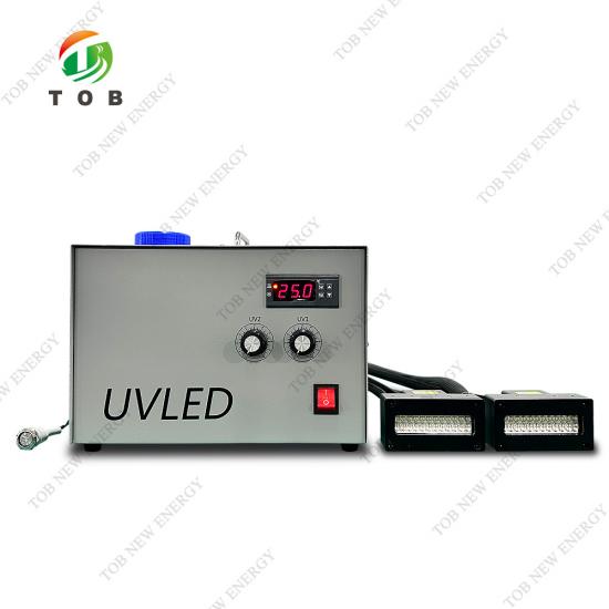
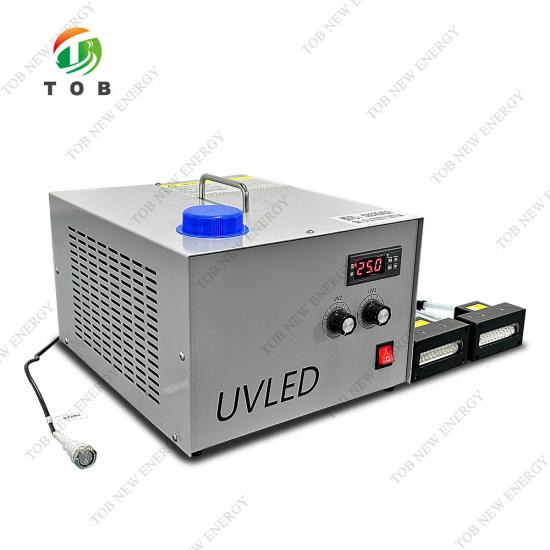
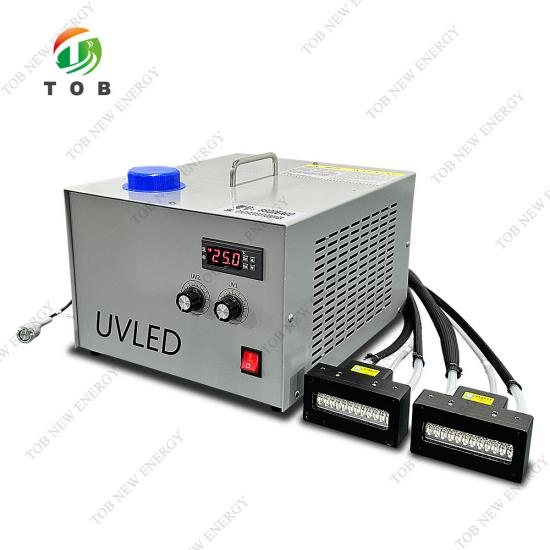
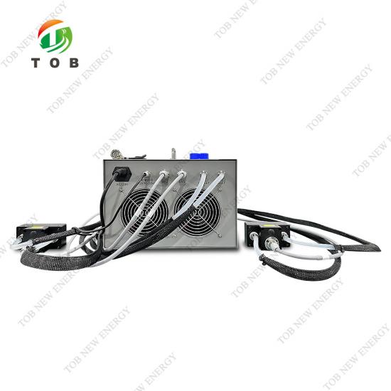
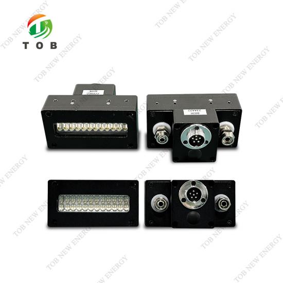
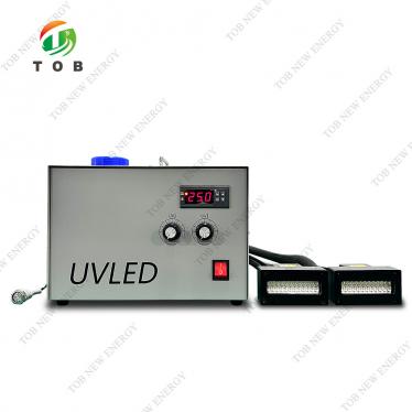
UV LED Curing System
Brand:
TOB NEW ENERGYitem no.:
TOB-S802EA02order(moq):
1Payment:
L/C,T/Tproduct origin:
Chinashipping port:
XIAMEN
TOB-S802EA02 High-Pressure Water-Cooled UV LED Curing System for Precision Bonding and Coating
Product Overview and Ideal Applications
A UV LED curing system uses semiconductor light‑emitting diodes to generate intense ultraviolet radiation at specific wavelengths, initiating a photochemical reaction that instantly hardens UV‑sensitive inks, adhesives, and coatings. Unlike conventional mercury‑vapour lamps that emit a broad spectrum with significant infrared (heat) radiation, the TOB‑S802EA02 delivers a concentrated output at 365 nm or 395 nm, with virtually no thermal radiation reaching the substrate. This fundamental difference translates into a cold curing process: the surface temperature of the irradiated part rises by only approximately 5 °C, whereas a mercury‑lamp system would typically raise it by 60–90 °C, causing thermal displacement, warping, and scrap.
The system is designed around a 600 W total power supply, driving a compact, lightweight irradiation head (0.5 kg) that can be mounted on robotic arms or fixed gantries. An industrial‑grade high‑pressure water‑circulation cooling circuit dissipates the heat generated by the high‑power LEDs, enabling continuous 24/7 operation without the output drift that plagues air‑cooled or passive‑cooled LED systems. The digital control interface offers potentiometer‑based brightness adjustment and DC 3–32 V signal start control, making it straightforward to integrate into automated production lines.
Ideal for:
- Battery manufacturing lines applying UV‑curable insulation coatings on electrode edges or sealing battery cells, where thermal stress on the electrolyte and separator must be avoided at all costs.
- Assembly of battery modules and packs, where structural adhesives and conformal coatings are dispensed and require immediate curing to maintain production cadence.
- Electronics, fibre‑optic, and medical device assembly where thermally sensitive components (e.g., plastic housings, lens elements) cannot tolerate the high heat of a mercury lamp.
- Digital inkjet printing on flexible substrates such as PVC and TPU, and in the decoration of building materials and toys where fast, low‑temperature curing maximises throughput and quality.
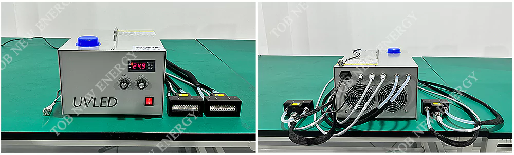
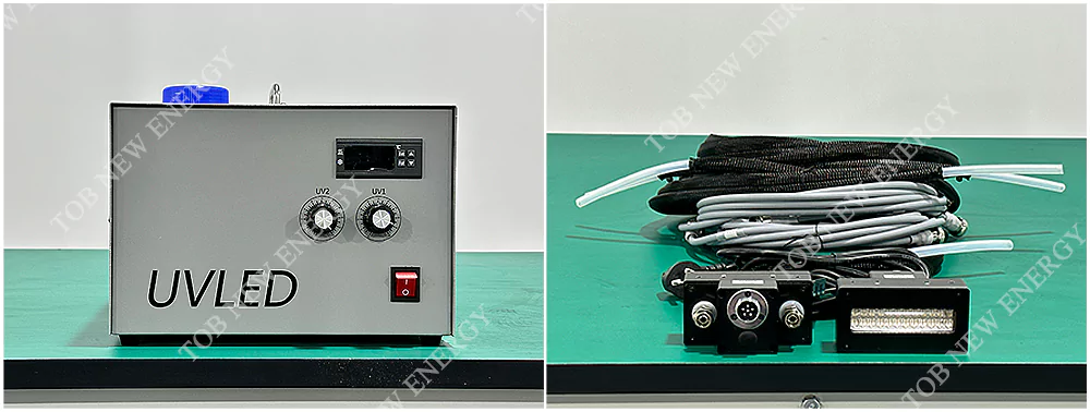
Where UV LED Curing Fits in Battery Manufacturing and Electronics Assembly
UV curing is a key enabling technology wherever a liquid resin, ink, or adhesive must be transformed into a solid, functional layer in seconds without applying heat. In the battery industry, the TOB‑S802EA02 can be deployed at several strategically important points:
- Electrode edge insulation: After the cathode and anode sheets are slit to size, the exposed foil edges are often coated with a UV‑curable insulating varnish to prevent internal short circuits. A mercury lamp would heat the foil, potentially degrading the binder at the electrode edge and causing delamination. The TOB‑S802EA02’s cold UV output cures the insulation instantly without disturbing the electrode structure.
- Battery cell sealing: Pouch‑cell and prismatic‑cell manufacturers use UV‑curable sealants to bond the cap or seal the final packaging layer. Traditional thermal curing can take minutes and requires large ovens; UV LED curing completes the bond in seconds, directly on the assembly line, reducing work‑in‑progress inventory.
- Module and pack assembly: Structural adhesives and thermally conductive gap fillers are increasingly UV‑curable to avoid the slow cure schedules of two‑component chemistries. The TOB‑S802EA02’s DC signal start control allows it to be triggered by a PLC, synchronising the UV pulse with the adhesive dispensing robot.
- Electronics and fibre‑optic interconnects: Many battery management system (BMS) components are assembled with UV‑cured conformal coatings or solder‑mask inks that protect the circuitry. The small irradiation window (80 mm × 20 mm) and adjustable working distance (3–7 mm) make the head suitable for targeting specific areas on a PCB.
In all of these applications, the defining advantage over a mercury lamp is the absence of infrared radiation. A 60–90 °C temperature spike is not merely inconvenient—it can distort plastic cell holders, degrade separator porosity, and accelerate electrolyte decomposition. The TOB‑S802EA02 eliminates this variable entirely, allowing process engineers to decouple the curing step from thermal management.
How the High‑Pressure Water‑Cooled UV LED System Works
The TOB‑S802EA02 converts electrical power directly into narrow‑spectrum ultraviolet light without the intermediate plasma‑heating stage required by a mercury bulb. Here is how the energy flows through the system:
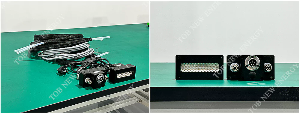
- LED light engine: The irradiation head contains an array of high‑power LED chips, each producing light at a centre wavelength of either 365 nm or 395 nm (the two standard options). The optical energy is focused through a precision lens window (80 mm × 20 mm) to deliver an intensity of 10–15 W/cm² at a working distance of 3–7 mm. Because the LEDs emit light only in the forward direction, no complex reflectors are needed, and almost all the generated UV reaches the target.
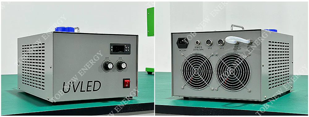
- Power and control: The power box (L360 mm × W304 mm × H202 mm) supplies up to 600 W total system power. The interface is a digital display with potentiometer‑based brightness adjustment, allowing the operator to dial in any intensity between the minimum and maximum. A DC 3–32 V signal input acts as the start trigger; this is commonly wired to a PLC or a limit switch, so the UV light fires only when a part is correctly positioned.
- High‑pressure water cooling: Each LED chip converts only a fraction of its electrical input into UV light; the remainder becomes heat that must be efficiently removed to maintain uniform light output and long LED life. The TOB‑S802EA02 uses a high‑pressure water‑circulation circuit that flows through a cold plate mounted directly to the LED substrate. The cooling capacity is sufficient to maintain the LED junction temperature well below its rated maximum, even when operating at full power continuously. The system includes a high‑temperature alarm and cut‑off protection: if the coolant flow is interrupted or the temperature exceeds the safe limit, the power supply is automatically shut down to protect the LED array.
Instant‑on, instant‑off operation
Unlike a mercury lamp, which requires a warm‑up period of several minutes and must be left running (or cycled through a shutter) between parts, the TOB‑S802EA02’s LEDs reach full intensity within microseconds of receiving the start signal and extinguish just as quickly when the signal is removed. This not only saves energy (the system is off when not actively curing) but also eliminates the need for mechanical shutters and their associated maintenance. The practical result is that the lamp can be fired exactly when needed, for exactly the duration required, and then shut off to preserve LED life—which, at 20,000–30,000 hours, is already an order of magnitude longer than a mercury bulb’s 800–3,000 hours.
Key Engineering Advantages of the TOB‑S802EA02
Cold Curing — Substrate Temperature Rise Only 5 °C
High‑power LEDs emit UV radiation at the target wavelength, but virtually no infrared energy. The heat that is generated within the LED chip itself is carried away by the water‑cooling circuit, never reaching the substrate. For battery electrodes and plastic components, this means the material remains dimensionally stable during curing, and temperature‑sensitive chemistries are preserved.
Life‑Span of 20,000–30,000 Hours Eliminates Frequent Lamp Changes
Mercury‑vapour lamps degrade steadily from their first ignition and typically require replacement after 800–3,000 hours. The TOB‑S802EA02’s LED array, operating at a controlled junction temperature, maintains over 90 % of its initial intensity for 20,000 hours or more. In a three‑shift production environment, this translates to several years of continuous service without changing a lamp—reducing maintenance labour, consumable costs, and production downtime.
Instant On/Off — No Warm‑Up, No Standby Power, and No Mechanical Shutter
The LED source responds to the DC start signal in microseconds. This means the system can be integrated into an indexed assembly line, firing only when a part is present, and remaining fully off between cycles. The energy savings compared to a continuously burning mercury lamp with a shutter are substantial, and the simplified mechanical design enhances reliability.
High‑Pressure Water Cooling Enables Continuous Full‑Power Operation
Air‑cooled and passive‑cooled UV LED systems suffer from output depreciation as the heat builds up, limiting their duty cycle or maximum power. The TOB‑S802EA02’s dedicated water‑cooling circuit maintains the LED array at a stable, low temperature regardless of the ambient environment (up to 35 °C), ensuring that the 10–15 W/cm² intensity is available hour after hour without derating.
Compact, Lightweight Irradiation Head (0.5 kg) for Easy Robot Integration
The small dimensions (L104 mm × W54 mm × H31 mm) and low weight allow the head to be mounted directly on a robotic arm or XYZ gantry. The working distance of 3–7 mm provides a comfortable clearance to avoid contact with the part while maintaining high intensity. Combined with the DC signal start, the head can be fully automated and synchronised with motion control.
Dual Wavelength Options (365 nm and 395 nm) for Versatile Curing Chemistry
Different photo‑initiators respond to different wavelengths. The TOB‑S802EA02 is available in a 365 nm configuration (for deep curing and through‑curing of clear materials) or a 395 nm configuration (for surface cure of pigmented and thick layers). The selection can be made at the time of order to match the specific adhesive or coating system.
Digital Control and Protection Systems
The interface provides a clear digital readout of operating parameters, while the high‑temperature alarm and cut‑off circuit protect the LED array from damage in the event of a cooling failure. The system also operates reliably in ambient temperatures from 10–35 °C and humidities from 20–85 %, making it suitable for factory floors as well as laboratories.
Complete Technical Specifications
| Parameter | Specification |
| Product Name | High‑pressure water‑cooled UVLED curing machine |
| Product Model | TOB‑S802EA02 |
| Input Voltage | AC 220 V |
| Cooling Method | High‑pressure water‑circulation refrigeration |
| Total System Power | 600 W |
| Single Lamp Holder Weight | 0.5 kg |
| Power Box Dimensions | L360 mm × W304 mm × H202 mm |
| Alarm Device | High‑temperature protection, cut‑off alarm device |
| Working Environment | Temperature 10–35 °C; Humidity 20–85 %; Storage temperature –15 °C to +65 °C |
| Optical Band | 365 nm / 395 nm |
| Optical Power | 10–15 W/cm² |
| External Dimensions of Irradiation Head | L104 mm × W54 mm × H31 mm |
| Illumination Head Window Size | L80 mm × W20 mm |
| Single Lamp Irradiation Power | 240 W |
| Appearance Interface Control | Digital display intelligent control interface |
| Brightness Adjustment Mode | Potentiometer knob |
| Start Control Mode | DC 3–32 V signal control |
| Working Height of Irradiation Head | 3–7 mm |
Why Choose TOB‑S802EA02 Over a Conventional Mercury‑Lamp UV System
| Feature | TOB‑S802EA02 UV LED Curing System | Typical Mercury‑Lamp UV System |
| Lamp life | 20,000–30,000 hours | 800–3,000 hours |
| Start‑up time | Instant (microseconds) | 2–5 minutes warm‑up |
| Standby / cycling | Can be switched off between cures; no mechanical shutter needed | Must be kept running or shuttered; shutter mechanism is a wear item |
| Substrate temperature rise | Approx. 5 °C | 60–90 °C |
| Infrared radiation | Virtually none | Significant; requires heat‑filtering or cooling |
| Energy consumption | Low; powers down between cycles | High; continuous operation plus cooling |
| Spectral output | Narrow band (365 nm or 395 nm), all energy in the useful UV range | Broad spectrum (UV, visible, IR), only a fraction is useful for curing |
| Maintenance | Minimal; periodic cleaning of window and coolant check | Frequent lamp changes, reflector cleaning, and ozone exhaust management |
| Hazardous waste | No mercury; LEDs are solid‑state and recyclable | Mercury‑containing lamps must be disposed of as hazardous waste |
| Integration flexibility | Compact, lightweight head; DC signal start for PLC control | Bulky lamp‑housing, requires high‑voltage ignition and shutter control |
Why battery manufacturers are switching to UV LED curing:
Mercury lamps were the industry standard for decades, but their drawbacks—short life, high heat generation, and environmental hazards—are becoming unacceptable in modern, high‑speed, low‑defect production lines. The TOB‑S802EA02 provides a direct replacement that not only solves these problems but also simplifies line integration. The cold UV output is particularly transformative for battery applications, where even a small temperature excursion can affect the cell’s formation cycle and long‑term reliability.
Engineering FAQ — UV LED Curing for Precision Assembly
Q1: How do I decide whether to use the 365 nm or 395 nm version?
The choice depends on the photo‑initiator chemistry of your resin or ink. Most clear UV adhesives and insulation coatings cure best at 365 nm, which provides deeper through‑cure. 395 nm is effective for surface cure of pigmented, white, or highly filled materials, as it is less absorbed and penetrates better. If your material supplier specifies a mercury‑lamp equivalent dose, the 365 nm head usually provides a closer spectral match to the short‑wavelength region of a mercury lamp. We can provide a sample head for cure‑speed testing if you send us your material.
Q2: What kind of water‑cooling infrastructure is required?
The TOB‑S802EA02 requires a closed‑loop high‑pressure water‑circulation system. This is typically provided by a standalone industrial chiller that pumps coolant (water or a water‑glycol mixture) through the lamp head at a controlled flow rate and temperature. The chiller should be sized to reject the lamp’s total electrical power (600 W) while maintaining a coolant supply temperature appropriate for the LED junction requirements (usually 20–25 °C). TOB can recommend compatible chillers or supply a complete system that includes the cooling unit.
Q3: Can the irradiation head be mounted in any orientation, or must it remain horizontal?
The head can be mounted in any orientation—horizontal, vertical, or angled—as long as the water‑cooling circuit remains free of air pockets. If the head is mounted with the window facing upward, special care must be taken during initial filling and bleeding to ensure that no air is trapped inside the cold plate. Once properly bled, the system operates reliably in any orientation.
Q4: Is the DC 3–32 V signal start compatible with standard 24 V PLC outputs?
Yes. Most industrial PLCs provide a 24 V DC digital output, which falls within the 3–32 V range. Simply wire the PLC output to the signal input terminals and program the PLC to energise that output whenever the UV light is required. The signal draws very little current, so a standard transistor or relay output works. If the system must be triggered by a mechanical switch, a small DC power supply (e.g., 12 V or 24 V) can be switched through a relay contact.
Q5: How do I know when the LED array has reached the end of its useful life and needs replacement?
The system does not fail abruptly; instead, the optical output gradually declines over years of use. An annual check with a UV radiometer (positioned at the working distance) is recommended. When the intensity at the working plane drops below the minimum required for your process (which you will have determined during initial process qualification), it is time to replace the LED module. The module is designed for relatively simple field replacement, and TOB can supply a pre‑calibrated replacement head.
Ready to replace your legacy mercury‑lamp curing station with a cold, instant, and long‑life UV LED system? Request a quotation for the TOB‑S802EA02 and specify your desired wavelength (365 nm or 395 nm). Our application engineers can also conduct a cure‑speed test with your specific adhesive or coating material.
tob.amy@tobmachine.com | +86 181 2071 5609
Previous:
Optical Fiber Laser Marking MachineNext:
Ultrasonic Cell Disruptor
If you are interested in our products and want to know more details,please leave a message here,we will reply you as soon as we can.

 subscribe to us