Chinese
 français
 Deutsch
 italiano
 español
 português
 Nederlands
 日本語
 한국의




- Home
- >
- Prismatic Cell Assembly Machine
- >
- Prismatic Cell Formation and Grading Machine
- >
- 16-Channel Negative Pressure Formation Machine for Prismatic Cell
Categories
Hot Products
Loading...
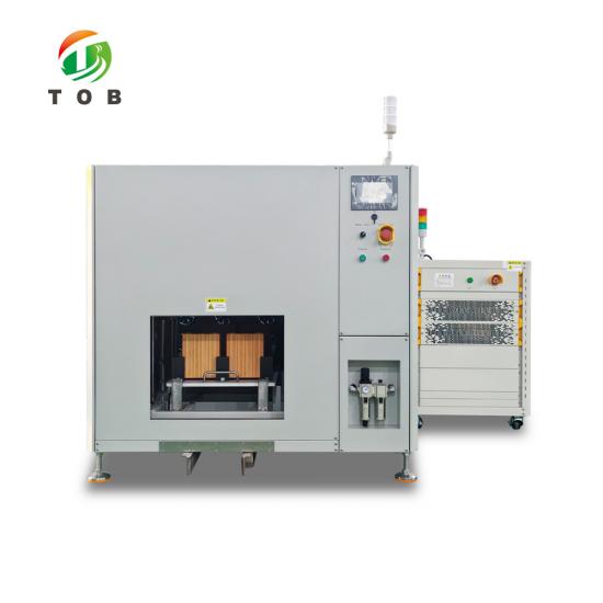
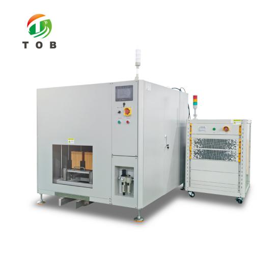
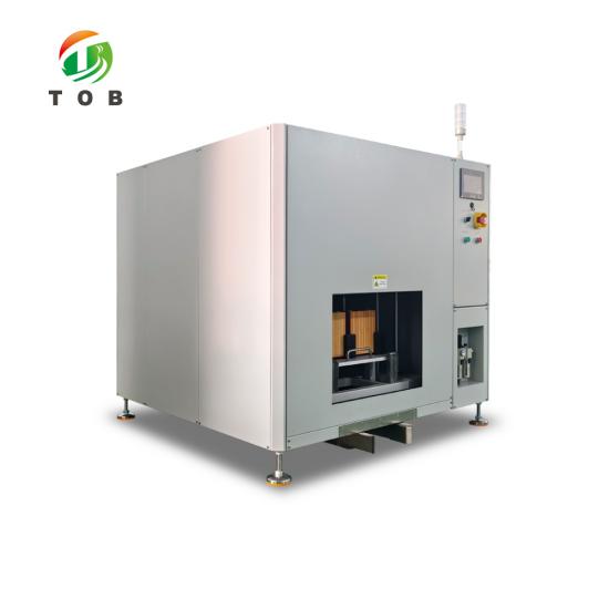
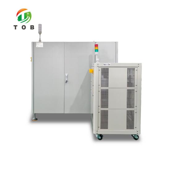
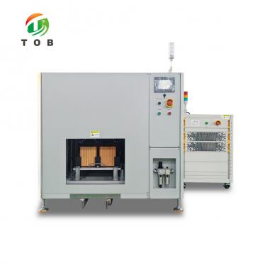
16-Channel Negative Pressure Formation Machine for Prismatic Cell
Brand:
TOB NEW ENERGYitem no.:
TOB-FH-5V60A-16CHorder(moq):
1setPayment:
L/C,T/Tproduct origin:
Chinashipping port:
XIAMEN
5V60A 16-Channel Negative Pressure Formation Machine for Prismatic Cell - TOB-FH-5V60A-16CH
Single-layer cabinet, sixteen channels at 5 V and 60 A, one 2 x 8 tray per section, with a leak-rate gate before charging and an automatic fire door
Product Overview and Ideal Applications
The TOB-FH-5V60A-16CH is a negative pressure formation cabinet for prismatic cells: sixteen channels at 5 V and 60 A in a single-layer, single-row cabinet, one machine-made tray per section arranged 2 x 8. Each channel presses a single sampling needle onto the tabs and seals a petal-shaped nozzle over the filler port, so charging and vacuum happen at one station.
Formation fixes the SEI, and the gas it produces has to leave while the cell can still vent at the port. This cabinet pumps down through the nozzle, condenses the solvent in a gas-liquid separator and returns the electrolyte when the vacuum is broken at atmospheric pressure. At 60 A the probe bed is the limiting part, so the contacts are gold plated and the drop is measured at the terminal. For fewer channels, see our 8-channels negative pressure formation machine for prismatic cell.
The cabinet stays under 2 m tall, loads the floor with no more than 1 t, and keeps the power cabinet separate so the formation side remains a five-sided enclosure. Two smoke sensors per unit cut the power, lift the probes off the cells and close the front fire door. Cell sizes run 95 to 218 mm wide, 27 to 73 mm thick and 148 to 175 mm high.
Ideal for:
- Prismatic cell lines, pilot or mass production, where formation and vacuum belong at one station.
- Cells 95 to 218 mm wide, 27 to 73 mm thick and 148 to 175 mm high, with a 204 x 71 x 173 mm blueprint cell as the reference.
- Processes that need a leak-rate gate before the first ampere: 0.3 kPa per minute over three minutes.
- Workshops where electrolyte loss and cross contamination must be bounded by design.
- Not for pouch or cylindrical cells, or where the current per cell exceeds 60 A.
Tell us your cell size, the formation current per cell and the delivery country. Our engineer will confirm the channel configuration, the tray layout and the negative pressure range before you order.
Complete the inquiry form below and our engineer will review your requirements. Prefer email? Contact tob.amy@tobmachine.com.
Complete Specifications
Figures below are the contracted values for the standard configuration. Where a requirement has a range, the range is the acceptance window at commissioning, not a target to be negotiated at delivery.
1. Cabinet, Channels and Electrical Rating
| Parameter | Value |
|---|---|
| Model | TOB-FH-5V60A-16CH |
| Channel rating | 5 V / 60 A per channel |
| Channels per cabinet | 16, single layer and single row |
| Tray per section | 1 tray per section, 2 x 8 arrangement |
| Loading and unloading | Manual, by tray |
| Cabinet enclosure | Five-sided enclosure with an automatic front fire door; normally open, closed on a fire alarm |
| Power cabinet | Separate from the press cabinet |
| Control | PLC, driving solenoid valves, buttons and indicator lights, with independent control of each mechanical unit |
| Monitoring | Temperature and smoke, continuous around the clock |
| Floor load | No more than 1 t |
| Overall height | Under 2 m |
2. Cell Compatibility and Changeover
| Item | Compatibility range | Blueprint model |
|---|---|---|
| Cell width (H) | 95 mm to 218 mm | 204 mm |
| Cell thickness (W) | 27 mm to 73 mm | 71 mm |
| Cell height (T) | 148 mm to 175 mm | 173 mm |
| Format changeover | Replace the lining within the compatibility range | - |
| Tray positioning accuracy | Within ± 0.5 mm | - |
| Press positioning accuracy | ± 2 mm, with ± 0.2 mm secondary positioning during the lift | - |
| Tray location method | Guide blocks on four sides plus diagonal positioning pins, with diagonal travel switch detection and a tray anti-reverse design | - |
The blueprint format quoted above is the cell the cabinet was set up against: 204 mm wide, 71 mm thick, 173 mm high. It sits in the press with the nozzle on the filler port and the probes on the tabs, which is the position every other format in the window has to be able to take.
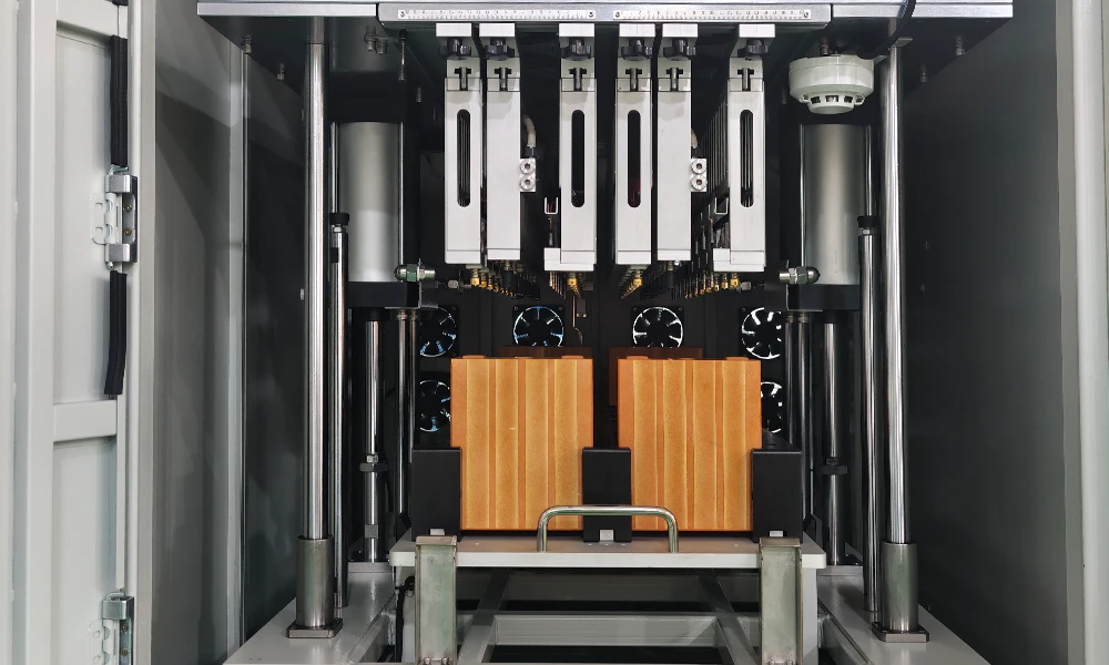
A 204 x 71 x 173 mm blueprint cell seated in the press during commissioning, nozzle down on the filler port and probes on the tabs.
3. Probe Bed, Contact and Temperature Sensing
| Item | Specification |
|---|---|
| Probe type | Single needle, switch type sampling needle |
| Probe assembly | Probe and temperature probe in one modular assembly, removable as a unit |
| Contact plating | Gold plated charge and discharge probes, selection based on contact resistance, heat generation and the 60 A maximum |
| Contact resistance | Sum of positive and negative contact impedance no more than 2 mΩ |
| Line loss | No more than 800 mV from the terminal to the power module connection end |
| Temperature rise at the joint | No more than 15 ℃ at 60 A for the whole formation cycle, measured in 25 ℃ natural cooling |
| Terminal indentation | No more than 0.1 mm on the positive and negative terminals |
| Probe life | At least 30,000 presses, or 3 years, in the designed working environment |
| Needle surface | Fine knurled pattern that does not scratch the terminal surface |
| Width adjustment | Left and right in the width direction, with a scale, to follow different tab spacings |
| Cable connection | Fast plug terminal blocks for both power and sampling cables |
| Temperature sensor | PT100, single point on the cell cover |
| Temperature accuracy | ± 1 ℃, with an adjustable acquisition frequency and a minimum sampling interval of 1 s |
| Screws | SUS304 stainless steel throughout the needle bed |
4. Negative Pressure Module Performance
| Item | Technical requirement |
|---|---|
| Suction nozzle positioning accuracy | Within 0.5 mm in all directions |
| Nozzle type and material | Petal-shaped flat contact nozzle in EPDM rubber, heat and electrolyte resistant, tolerant of cell unevenness up to 1 mm |
| Nozzle life | At least 500 cycles, replaced every 3 months |
| Negative pressure cup | At least 60 ml, eccentric with a sloping bottom, anti-rotation design, double-layer sealing rings and a filter screen |
| Vacuum range | -90 kPa ± 5 kPa, suitable for both high and low vacuum adjustment |
| Pressure gauge | Digital gauge on the front-end pipeline bypass, -100 kPa to 100 kPa, vacuum data written into the tray record |
| Leak rate | No more than 0.3 kPa per minute, measured over a three-minute hold after the vacuum source is closed |
| Vacuum fluctuation | No more than ± 3 kPa at the set value, in the two stages before and after formation is started |
| Pumping speed | At least 5 kPa per minute from 0 kPa to -80 kPa, adjustable |
| Release speed | At least 5 kPa per minute from -80 kPa to 0 kPa |
| Impurity filtration | Corrosion resistant, easy to replace, dust-free filter at the vacuum breaking inlet of each module |
| Electrolyte collection cup | At least 600 ml, with a cup full alarm |
| Electrolyte loss caused by the equipment | Less than 2 g, with no residual electrolyte left at the bottom of the buffer device |
| Vacuum pump | GWSP75 oil-free vacuum pump, one set supplied with the machine |
5. Safety, Interlocks and Monitoring
| Function | How it behaves |
|---|---|
| Smoke detection | Two sensors per mechanical unit, one gas-sensitive and one particle type |
| Action on smoke | Power is cut immediately, the cylinder opens to separate the battery from the probe, and an alarm is raised |
| Fire door | Front door closes automatically on a fire alarm; the front panel is sealed against smoke and fire |
| Power or air failure | The lifting platform is not allowed to descend without reason, including an abnormal solenoid valve or abnormal air pressure |
| Tray in place | Travel sensor inside the press bed, reporting tray position in real time, with protection and alarm |
| Tray anti-reverse | Mechanical design plus diagonal travel switch detection, so a reversed tray is detected rather than pressed |
| Sequence fool-proofing | The probe makes contact before the nozzle leaves, and the nozzle leaves before the probe makes contact again |
| Tray bottom stress | Uniform loading during the lift, so the tray does not deflect and disturb the formation |
| Maintenance access | Probe, negative pressure and temperature modules can be removed individually; probe components are plug-in and scale marked |
| Liquid collection | Removable liquid receiving tray under the press storage area, for electrolyte dripping from the nozzles |
6. Standard Supply and Spare Parts
| Group | Item | Qty |
|---|---|---|
| Machine | Single layer single row cabinet, five-sided enclosure with fire door | 1 set |
| Machine | Mechanical unit, 16 channels in a 2 x 8 arrangement | 1 set |
| Machine | Smoke sensors | 2 sets |
| Machine | Temperature sensor | 1 set |
| Machine | Negative pressure control system | 1 set |
| Other | GWSP75 oil-free vacuum pump | 1 set |
| Vulnerable parts | Probe | 10 pcs |
| Vulnerable parts | Temperature probe | 10 pcs |
| Vulnerable parts | Negative pressure suction nozzle | 300 pcs |
| Vulnerable parts | Negative pressure cup | 10 pcs |
| Negative pressure module | Molecular sieve | 1 pc |
| Negative pressure module | Gas-liquid separator | 1 pc |
| Negative pressure module | FRL unit | 1 pc |
| Negative pressure module | Residual liquid cup | 1 pc |
Equipment quantity and spare part quantities are confirmed against the commercial contract. Where the specification states a range, the acceptance value is the one written into that contract.
Machine Layout and Working Principle
The cabinet is one layer, one row, sixteen channels, and one machine-made tray per section laid out 2 x 8. The tray is loaded and unloaded by hand, which is deliberate: at sixteen channels the tray is the unit of traceability, so a tray that has to be lifted out is also a tray whose record can be checked before it goes back in.
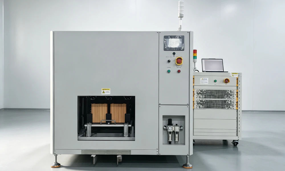
The cabinet on a production floor: formation side on the left, negative pressure control system on the cabinet side, power cabinet split off.
Inside the press the mechanical unit travels from bottom to top while the probe board stays still and the tray moves. The probe wires and the air pipes therefore do not travel with the tray, which removes the flexing that normally turns a cable into a consumable. The tray is located twice: guide blocks on four sides plus diagonal positioning pins bring it to within ± 0.5 mm, and a secondary guide holds ± 0.2 mm while the platform lifts, so the nozzle meets the filler port squarely instead of being pulled into alignment by the rubber.
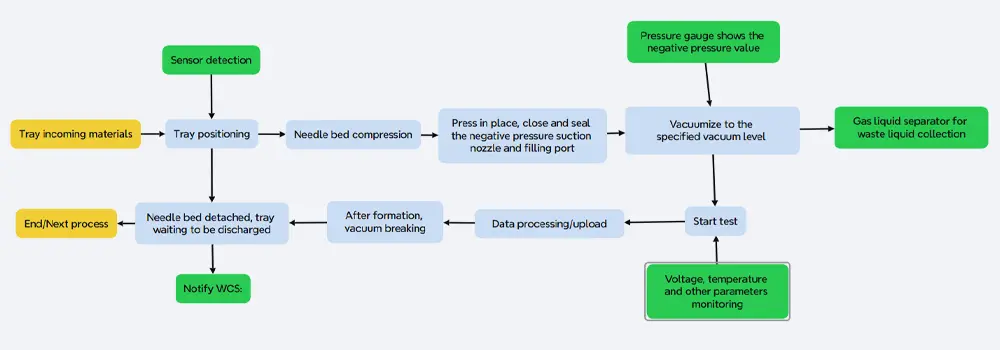
The sequence the PLC runs: tray located, nozzle sealed on the port, leak test passed, vacuum and current applied together, vacuum broken at atmospheric pressure, electrolyte returned, tray released.
The bottom of the tray is loaded uniformly during the lift. That requirement exists because a tray that deflects under the press changes the stack pressure on the cells in the middle of a formation cycle, and a cell that is pressed harder than its neighbours charges at a different rate. For the same reason the tray lift height is adjusted by a mechanical limit stop, which cannot drift after a software update.
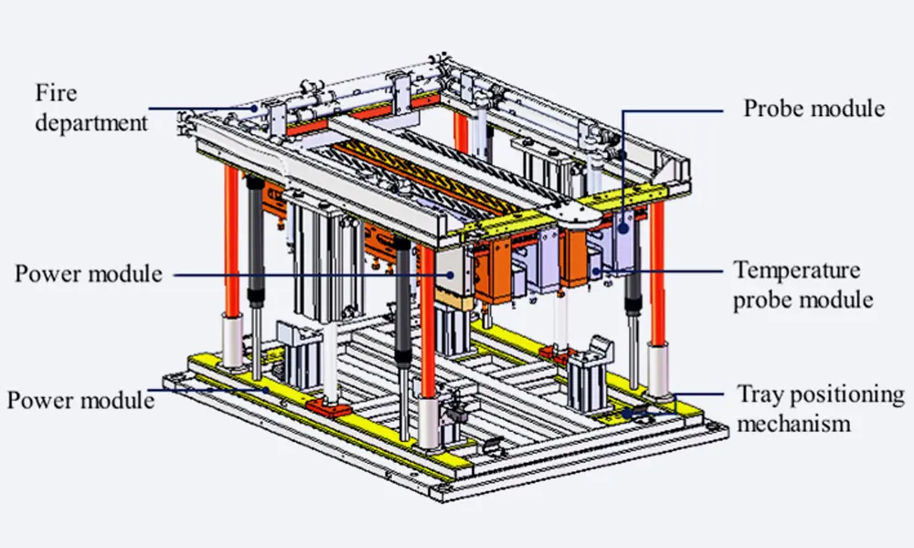
The press module: guide blocks and diagonal pins locate the tray, the travel sensor sits inside the press bed, and the lifting height is set by a limit rather than by a program value.
A travel sensor inside the press bed reports whether the tray is actually in place, and a diagonal travel switch on the anti-reverse design catches a tray that has been turned. Both report before the cylinder is allowed to close, so a misplaced tray is refused rather than pressed.
Probe Bed and Contact System
At 60 A per channel the contact is the part that decides whether the formation data is worth keeping. A contact that is merely adequate will heat, and a joint that heats changes resistance, and a resistance that changes shows up in the recorded voltage as a cell that behaved differently from its neighbours. The probe bed is therefore specified around the joint, not around the needle.
The charge and discharge probes are gold plated, chosen against three constraints at once: contact resistance, heat generation and the 60 A maximum. The sum of positive and negative contact impedance is held at or below 2 mΩ, the line loss from the terminal to the power module connection end at or below 800 mV, and the temperature rise at the joint at or below 15 ℃ across the whole formation cycle, measured in 25 ℃ natural cooling. Contact resistance and tab voltage are displayed in real time, so a joint that is starting to go is visible as a number before it becomes a scrap tray.
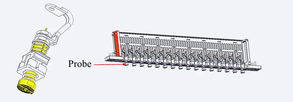
One needle per polarity, carried in a module that also holds the PT100. The module slides on a scale so the pair can follow a different tab spacing.
The needle surface is finely knurled, and the pattern is specified so that it does not scratch the terminal. The indentation limit is 0.1 mm on both terminals, which is the practical dividing line between a witness mark and a stress riser at the weld. Service life is at least 30,000 presses, or 3 years, whichever comes first, and the non-metallic parts of the probe are required to last at least as long as the probe itself.
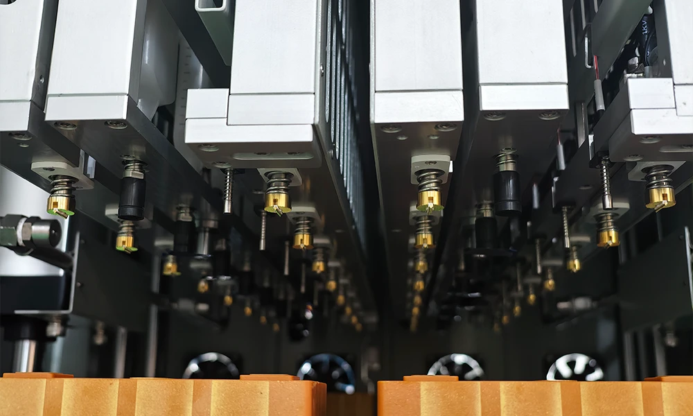
The probe as used at 60 A: a single gold-plated needle, knurled at the tip, with the temperature probe carried in the same modular assembly.
Everything that wears is modular. The probe, the negative pressure and the temperature assemblies can each be taken out on their own; the probe components are plug-in and marked with a scale, so the width position can be restored after a replacement without a gauge. Power and sampling cables land on fast plug terminal blocks. All screws in the needle bed are SUS304, which matters in a room where electrolyte mist is present.
Temperature is read by a PT100 on a single point of the cell cover, accurate to ± 1 ℃. The acquisition frequency is settable by temperature band, with a minimum sampling interval of 1 s, so a step that runs hot is sampled more often than a step that does not.
Negative Pressure Module: Nozzle, Cup and Leak Test
The nozzle, the connecting rod and the negative pressure cup are one integrated part, which is what keeps the sealing face from being disturbed every time the cup is serviced. The nozzle is a petal-shaped flat contact piece in EPDM, pressed onto the cap rather than pushed into the port, and it tolerates up to 1 mm of unevenness across the cap surface. Nozzle life is at least 500 cycles and the practical replacement interval is three months.
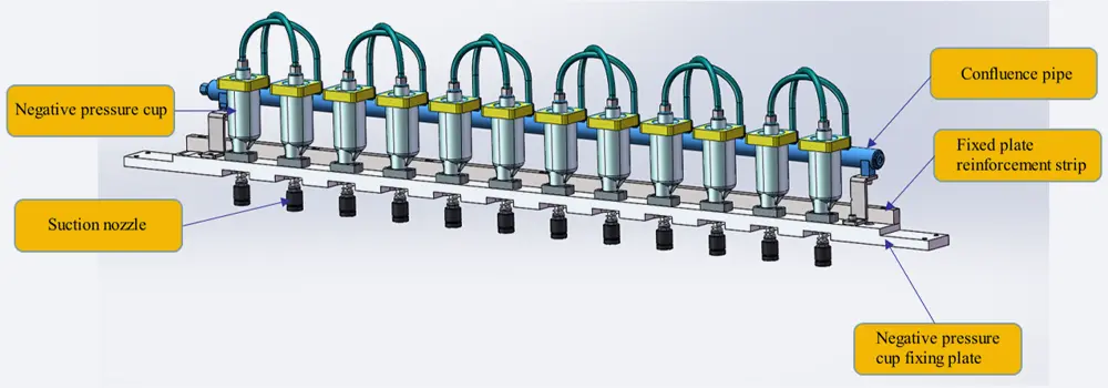
Nozzle, rod and 60 ml cup as one assembly. The cup is eccentric with a sloping bottom so that electrolyte drains instead of sitting in a corner and crystallising.
The cup holds at least 60 ml and is designed against rotation, because a cup that can turn will eventually unscrew itself against a fixed tube. It uses double-layer sealing rings and a filter screen, and its eccentric sloping bottom keeps residual electrolyte moving towards the drain. Each module draws through a proportional control valve, so the vacuum value can be changed during a step rather than only between steps.
Behind the module, the vacuum line carries a gas-liquid separator and a buffer tank ahead of the solenoid valve, with a manual valve at the bottom of the buffer tank to discharge what has been collected. A one-way valve stops gas pulled out during formation from flowing back into the cell. The collection cup holds at least 600 ml and raises a cup full alarm, and the separated liquid is required to leave the separator quickly rather than stand in it.
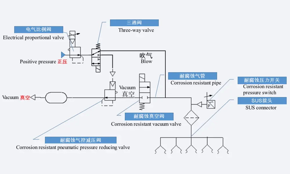
Reference layout of the control side: separator and buffer ahead of the valve, one-way valve against backflow, collection cup with level alarm, and the digital gauge on the bypass.
Every module has to prove itself before it is allowed to charge. The test pumps to the set vacuum, closes the source, holds for three minutes, and requires the decline to stay at or below 0.3 kPa per minute; the pass mark is set on the power software screen, and formation cannot start until it is met. During the run the vacuum may not fluctuate by more than ± 3 kPa at the set value across the two stages either side of the start of formation. Modules are not allowed to interfere with one another, so one channel pulling down cannot depress the vacuum of a neighbour that is already forming.
When formation ends, the vacuum is broken with drying gas at atmospheric pressure and the electrolyte that was drawn out returns to the cell. Equipment-caused electrolyte loss has to stay under 2 g, with nothing left standing at the bottom of the buffer. After the nozzle lifts off the cell, the system holds a micro negative pressure so that the drop hanging on the nozzle does not fall onto the cap. The vacuum breaking inlet carries a filter, and the storage area below the press has a removable liquid receiving tray.
The control system is mounted on the side of the cabinet, out of the formation zone. Pumping speed, release speed and vacuum value are all settable per step, the vacuum and the charge-discharge program can be run separately or driven from the host software, and the vacuum data is written into the tray record. The digital gauge reads -100 kPa to 100 kPa on a bypass at the front of the line, where it can be seen without opening anything.
Key Engineering Characteristics
- 60 A through one gold-plated needle: contact impedance at or below 2 mΩ, line loss at or below 800 mV and a joint rise at or below 15 ℃, with the values displayed while the cell is forming.
- A leak-rate gate before the first ampere: three minutes at the set vacuum with a decline of no more than 0.3 kPa per minute, or formation does not start.
- A 60 ml cup that drains itself: eccentric body, sloping bottom, anti-rotation location, double seals and a filter screen, so electrolyte leaves instead of crystallising at the bottom.
- Electrolyte comes back to the cell: vacuum is broken with drying gas and the drawn-out electrolyte returns, with equipment-caused loss held under 2 g.
- Two smoke sensors per unit and a door that closes itself: gas-sensitive plus particle detection, power cut, cylinder opened to lift the probes off the cells, alarm raised and the front fire door closed.
- A platform that will not drop: on power loss, an abnormal solenoid valve or abnormal air pressure the lifting platform holds its position rather than descending onto the tray.
- A probe bed set by scale, not by feel: modules slide left and right against a marked scale, lift height is set by a limit stop, and every wearing part comes out on its own.
- A 2 x 8 tray that cannot be loaded backwards: guide blocks, diagonal pins, diagonal travel switch detection and a travel sensor in the press bed, locating to ± 0.5 mm and holding ± 0.2 mm through the lift.
Why Prismatic Cells Are Formed Under Negative Pressure
The first charge builds the SEI, and it does so while the electrolyte is decomposing at the anode surface. That decomposition produces gas. In a hard-case cell the gas has nowhere to go until the port is sealed, so the question is not whether it forms but at which moment it leaves and what it takes with it. Formation under negative pressure answers both: the gas is pulled out through the filler port while the cell is still open, and the vapour that comes with it is condensed rather than lost to the room.
Pulling vacuum at the port also holds the cell in a state where the internal pressure is below ambient. That does two things at once. It keeps the gas moving towards the port rather than letting it accumulate against the separator, and it holds the electrolyte that has been drawn into the nozzle and the cup instead of letting it fall back onto the cap. A cell formed at ambient pressure will still work; it will simply carry a gas bubble and a wet cap into the next process, and both show up later as a cosmetic reject or a capacity spread that nobody can attribute.
The vacuum and the charge are set separately on this cabinet, and that separation is the point. Withdrawing gas is a plumbing operation with its own timing; charging is an electrical one. A machine that ties them together forces the process engineer to compromise on whichever of the two is less convenient. Here the pumping step, the breaking step and vacuum cycling can each be programmed, or handed to the host software, while the seal at the nozzle is maintained throughout so that neither activity disturbs the other. If you are comparing cabinet styles rather than channel counts, the negative pressure formation machine for prismatic cell covers the same formation stage and is worth reading side by side with this one.
The leak test exists because vacuum that holds for a second and vacuum that holds for a cycle are not the same claim. Three minutes at the set value with a decline of no more than 0.3 kPa per minute is long enough for a slow leak at a seal face to show, and short enough that it can be run before every tray instead of on a sample. A seal that fails this test is going to admit air during formation, and air at the anode during the first charge is exactly the condition that produces a dry spot and a cell that tests low. Blocking the start is cheaper than explaining the tail of the distribution later.
What leaves the cell is not only gas. Electrolyte vapour condenses in the line, and condensed electrolyte in the wrong place is a slow failure: it crystallises at a corner, it blocks a bore, and it eventually travels back. That is why the cup is eccentric with a sloping bottom rather than a cylinder, why the line carries a one-way valve, and why the separator is required to discharge quickly instead of storing what it has separated. Cross contamination between channels is excluded by design for the same reason, because a shared manifold would let one cell's electrolyte become another cell's impurity.
Sixteen channels at 60 A in one layer is a footprint decision as much as an electrical one. The cabinet stays under 2 m tall, puts no more than 1 t on the floor and keeps the power cabinet separate, which is what allows it to sit in an existing dry room instead of a new one. Where the line needs the energy of formation recovered rather than dissipated, that is a different cabinet: see the energy feedback lithium battery formation machine. This one is built around the vacuum path and the contact, not around the energy balance.
Operating Recommendations, Maintenance and Safety
1. Before the first tray of a batch
- Check the lining against the cell in hand. The compatible window is 95 to 218 mm wide, 27 to 73 mm thick and 148 to 175 mm high; a cell inside the window but at a different format still needs the lining changed.
- Confirm the probe pair against the tab spacing on the scale, then press one cell by hand and read the contact resistance before loading a full tray.
- Run the leak test with an empty or dummy tray and watch the decline, not the absolute value: 0.3 kPa per minute over three minutes is the pass mark.
- Drain the buffer tank and check the collection cup level. A cup that is nearly full will alarm mid-cycle and interrupt a tray that is already charging.
- Verify that the nozzle seats on the cap without being forced. The nozzle tolerates 1 mm of unevenness; a cap outside that needs the cell checked, not the nozzle tightened.
- Test the smoke sensors and the fire door with the tray empty, so that the first time the door closes is not the first time anyone sees it close.
2. Changeover to a different cell format
- Change the lining first, then re-set the probe width on the scale, then re-set the tray lift height by its limit stop. Doing it in the other order means the lift is set against a lining that is about to move.
- Re-run the leak test after any change to the nozzle or the cup, because a reseated nozzle is a new seal face.
- Re-check the ± 0.5 mm tray location with a first article, and the ± 0.1 mm indentation on both terminals, before releasing the format to production.
3. Maintenance and safety
- Replace the suction nozzle on the three-month interval even if it has not reached 500 cycles. EPDM that has swollen does not fail visibly, it just stops sealing under vacuum.
- Clean the liquid receiving tray under the press storage area on a fixed schedule. It is the place where a slow nozzle drip becomes a corrosion problem.
- Replace the filter at the vacuum breaking inlet when the pumping speed falls below 5 kPa per minute from 0 to -80 kPa, not when it blocks completely.
- Track probe life in presses rather than in months: 30,000 presses or 3 years, whichever comes first, and the non-metallic parts are specified to last at least as long.
- Never defeat the sequence interlock that keeps the nozzle on the port until the probe has made contact. It is there because the alternative is an arc at a wet cap.
- Keep the cabinet side clear. The negative pressure control system sits there deliberately, both to protect it from the formation zone and so that maintenance does not require opening the press.
Certification, Patents and Delivery Record
1. Management system certificates
The factory that builds this cabinet holds ISO 9001 certification under 3050260408100Q, issued on 8 April 2026 and valid to 7 April 2029, together with ISO 14001 (305026082585E) and ISO 45001 (305026082584HS) for environmental and occupational safety management. The certified scope covers laboratory, pilot line and production line machines together with battery materials and technologies, which is the scope this cabinet falls inside.
On site assessment of the factory has also been carried out by SGS (report 19520939_T) and TUV (report 493330274_T) through Alibaba.com supplier verification. Those reports attest the factory and its capability; they are not a conformity assessment of any individual machine, and we do not present them as one.
On CE marking we are explicit rather than convenient: no CE certificate is currently held for the TOB-FH-5V60A-16CH. A certificate attaches to the model designation printed on the nameplate, not to a product family, so it cannot be borrowed from a sister machine, and we do not show one that does not exist. If CE marking is a purchasing requirement, say so at enquiry stage: this model can be put through conformity assessment and certification for the destination market on request, and the quotation will state what is involved rather than leaving it to the delivery schedule.

|

|

|
2. Patents held by the founder
Dany Huang, Ph.D., founder and CEO of TOB NEW ENERGY, holds 55 Chinese patents: 5 granted invention patents, 45 utility model patents and 5 published applications. He entered the industry in 2002 through pouch cell materials, then cylindrical cells, then prismatic aluminium shells, and founded the company in 2012.
The patents sit on the cell side rather than the machine side. They cover cell structures, formulations and gas handling, and none of them is a patent on this cabinet. We state that boundary because a patent count is only useful if the reader knows what it is a count of.
3. Research record
Our citation index holds 707 records that reference TOB equipment or materials, 612 of them with a DOI. 70 of those records name a specific TOB model in the experimental section. None of the 70 names the TOB-FH-5V60A-16CH; this cabinet is new to the index, and we would rather say so than attach a citation that belongs to another machine.
Where a model is named in a paper, we cite the paper as evidence that the equipment was used, not as evidence of what the equipment can do. The findings in those papers belong to their authors, and the citation is to the machine, not to a performance claim.
4. Reference projects
Two delivered projects show the scale at which this stage of the process is built. Both are pouch and cylindrical lines rather than prismatic, and we say so because the formation stage is the same engineering problem in each: gas has to leave, electrolyte has to come back, and the record has to survive the tray.
A European customer's 20MWh automated high-flexibility Li-ion and Na-ion pouch cell mass production base runs at roughly 100,000 cells a year across a 1,500 m² footprint that includes a dedicated formation workshop, with hot-press formation equipment and formation-side degassing in the same route.

Formation equipment inside the 20MWh formation workshop, where the vacuum and temperature record is tied to the tray rather than to the shift.
A 32140 tabless cylindrical cell production line with stainless-steel cans delivered in Europe treats formation and sorting as one production step, with formation, aging, testing, grading and sorting kept on a connected record so that a cell can be traced back to its lot.
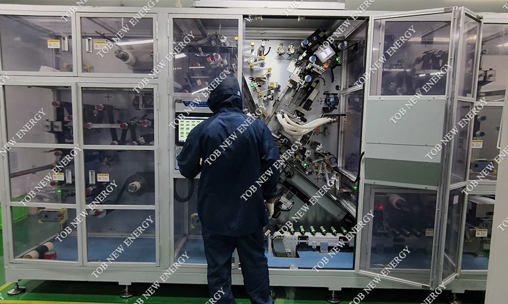
Commissioning on site in Europe, where the back end of the line includes formation, aging, testing, grading and sorting as one traceable step.
Engineering FAQ
Q1: Why run formation under negative pressure instead of forming first and degassing afterwards?
Because the gas is produced during the first charge, not after it. Degassing a finished cell means waiting for the gas to collect and then removing it through a path that has already been sealed once. Pulling vacuum at the filler port removes it as it forms, and the vapour that leaves with it can be condensed and returned instead of being vented to the room.
Q2: What does the 0.3 kPa per minute leak test actually catch?
It catches a seal that holds at the moment of contact but leaks under a sustained pressure difference, which is the failure mode a quick vacuum check misses. The test pumps to the set value, closes the source, and watches for three minutes; a decline above 0.3 kPa per minute blocks the start. That threshold is set in the power software, so a process engineer can tighten it per product without touching the plumbing.
Q3: Why is the negative pressure cup 60 ml when the collection cup is 600 ml?
They do different jobs. The 60 ml cup sits directly under the nozzle and is the place where electrolyte first condenses, so it has to be small enough to keep liquid moving and shaped so that it drains: eccentric body, sloping bottom, anti-rotation location. The 600 ml cup is the collection vessel behind the gas-liquid separator, with a level alarm, and it is sized so that a shift of trays does not fill it mid-cycle.
Q4: Can one cabinet run sixteen channels at 60 A for a full formation cycle?
That is what the contact specification is written for: 60 A with the joint temperature rise held at or below 15 ℃ in 25 ℃ natural cooling, contact impedance at or below 2 mΩ and line loss at or below 800 mV across the whole cycle. The power cabinet is separate from the press cabinet for the same reason, so that the heat of the electrical side does not sit inside the formation enclosure. Contact resistance and tab voltage are displayed while the cycle runs, which is the practical way to know whether a particular tray is still inside that envelope.
Q5: Where does the electrolyte that is pulled out of the cell go?
It condenses in the cup and the line, collects in the buffer tank and the collection cup, and returns to the cell when the vacuum is broken with drying gas at atmospheric pressure. Equipment-caused loss is held under 2 g, and the buffer is required to have nothing left standing at its bottom. A one-way valve stops what has been pulled out from flowing back, and cross contamination between channels is excluded rather than managed, because a shared manifold would turn one cell's electrolyte into another cell's impurity.
Q6: How is a change to a different cell format carried out?
By changing the lining, then re-setting the probe width on its scale, then re-setting the tray lift height on its limit stop, and finally re-running the leak test and a first article. The compatible window is 95 to 218 mm wide, 27 to 73 mm thick and 148 to 175 mm high, with a 204 x 71 x 173 mm blueprint cell as the reference. A cell that fits the window but not the lining still needs the lining changed; the window is not a substitute for the changeover.
Q7: When is this cabinet the wrong choice?
When the cell is pouch or cylindrical, when the formation current per cell is above 60 A, or when the line needs the energy of formation recovered rather than dissipated. It is also the wrong choice if the process requires formation and vacuum to be separate operations with independent handling, since the point of this cabinet is that they happen at one station. In each of those cases the constraint is the process, not the price, and it is better to say so before a specification is written around the wrong machine.
Tell us the cell size, the formation current and the vacuum your process already uses, and we will confirm the channel configuration, the tray layout and the leak-rate setpoint before you order, so the first tray you run is one you can repeat.
Email: tob.amy@tobmachine.com | Mobile phone: +86-18120715609
Reviewed by: Science Wang, Six Sigma Black Belt, Battery Lines | Last updated: 2026-11-10
Previous:
5VMax240A Lithium Prismatic Cell Formation and Grading MachineNext:
8-Channels Negative Pressure Formation Machine for Prismatic Cell
If you are interested in our products and want to know more details,please leave a message here,we will reply you as soon as we can.


 subscribe to us