Chinese
 français
 Deutsch
 italiano
 español
 português
 Nederlands
 日本語
 한국의




- Home
- >
- Electrode Preparation
- >
- Battery Slurry Mixer
- >
- Double Planetary Vacuum Mixer for Glovebox
Categories
Hot Products
Loading...
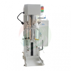
Double Planetary Vacuum Mixer for Glovebox
Brand:
TOB NEW ENERGYitem no.:
TOB-PVM-2Lorder(moq):
1setPayment:
L/C,T/Tproduct origin:
Chinashipping port:
XIAMEN
Double Planetary Vacuum Mixer for Glovebox Operation - TOB-PVM-2L
2 L jacketed double planetary mixer, 0.75 kW mixing and 1.5 kW dispersion, split head and cabinet so the machine runs inside an inert glovebox
Product Overview and Ideal Applications
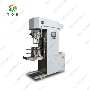
The TOB-PVM-2L is a 2 L double planetary vacuum mixer built to be operated inside a glovebox. Mechanically it is a cantilever-beam machine: two mixing shafts on a planetary gearbox, two high-speed dispersion shafts and a single wall scraper run into a 180 mm diameter by 130 mm high SUS304 vessel, jacketed for cooling water, sealed for vacuum down to -0.098 MPa. The mixing blades are cast in one piece and then machined and polished, which is what allows the 2 to 4 mm bottom clearance, the 2 to 5 mm wall clearance and the 3 to 10 mm blade-to-blade clearance in the specification table to be held as tolerances rather than as best efforts.
What separates this machine from a bench-top planetary mixer is not the vessel size, it is the split. The mixing head and the control cabinet are two separate bodies. Only the head and the vessel go inside the inert atmosphere; the cabinet sits on a stand under or beside the box, outside the sealed volume, and is connected back through the wall. That single decision carries most of the glovebox argument on this page. The electronics, the variable frequency drives and their heat stay out of the box. The operator works the HMI without breaking the seal or putting a hand through a port. And the machine that remains inside is small enough, at 640 x 450 x 780 mm, to leave working room around it in a standard single or dual-station box.
Three features exist specifically because the machine runs in a box rather than on a bench. The lift is manual, driven by a handwheel on the side of the column, so no compressed air line has to be brought through the wall and there is nothing pneumatic to leak into the atmosphere. A spotlight is fitted to the head, because a glovebox interior is dark and the most common reason operators lift the lid is to look at a slurry they cannot see. And the cooling jacket runs on water through G1/2 ports rather than on a refrigerant circuit, so the only utilities crossing the wall are water, vacuum and power.
The process reason to put mixing inside a box is straightforward: some slurries cannot be exposed to air at any stage, and transferring a mixed batch out of a sealed mixer and into a cell is exactly the step where exposure happens. Mixing, degassing and holding the slurry under vacuum in the same atmosphere the cell is assembled in removes that transfer. The 2 L effective volume, against a 3 L design volume, leaves a two thirds fill ratio, which is the working range a planetary mixer needs to let the blades travel and to leave headspace for the foam the vacuum has to pull down.
Ideal for:
- Mixing and degassing slurries under inert atmosphere when the batch cannot be exposed to air between mixing and coating or assembly
- Solid-state, lithium-sulfur and sodium chemistries whose active material, electrolyte or solvent is handled inside a glovebox throughout
- Lab and pilot lines where the mixer has to live inside the box permanently rather than be carried in and out
- Formulations that need staged speed and vacuum profiles, and a jacketed vessel to hold the batch temperature while they run
- Retrofits into an existing box, where a low, narrow machine and an external cabinet are the only way to fit a planetary mixer at all
Two boundaries are worth stating before the specification. The mixer is supplied without the glovebox; the box in the drawings on this page is there to show the arrangement, and if you need the enclosure as well it is a separate item, of which the single workstation lab equipment glove box is the smallest version we build. And this is a 2 L development and pilot machine: at 2 L per batch it is the wrong tool for a production line, where the same mixing principle is available at 30 L and well beyond. Between the two there is a bench version of the same capacity that does not have the split cabinet, so if your process is not confined to a box, the 2 L laboratory planetary vacuum mixer is the more direct answer, and below it the 500 ml compact dual-shaft mixer covers early formulation work.
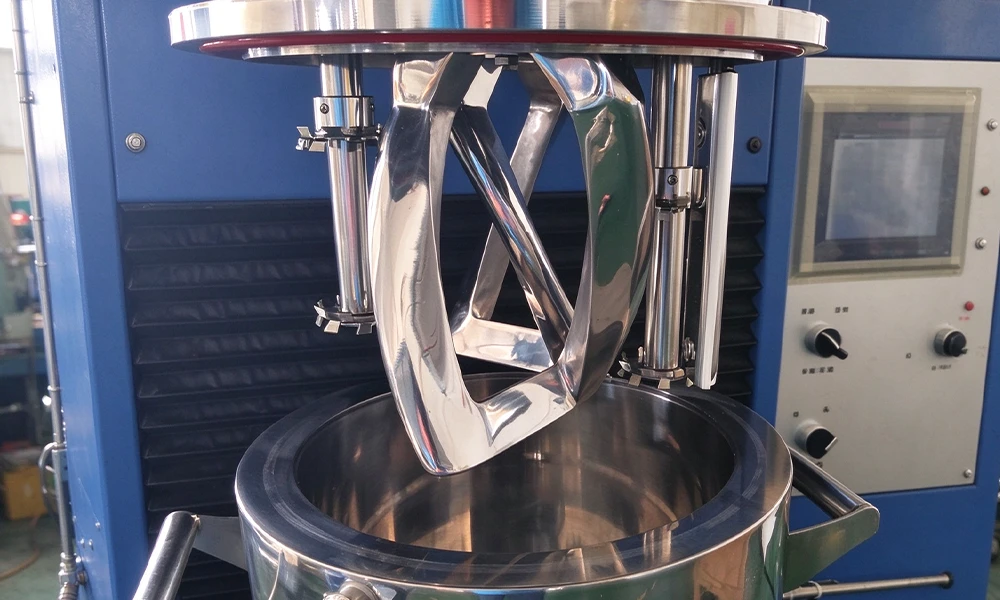
The mixing head raised clear of the vessel: the cast frame blade, a dispersion shaft with its plate, the PTFE wall scraper on the right, and the vessel with its two handles and lid seal.
Complete Specifications
The tables below are the datasheet for the machine, reproduced without rounding. Readings marked as maximum are the drive limits at 50 Hz; the working range is set in the recipe. Where a value is a clearance it is given as the acceptance window, because on a planetary mixer the clearance between blade and vessel is what decides whether the batch is mixed or smeared.
1. Machine, Drive and Vacuum
| Item | Parameters |
|---|---|
| Body structure | Cantilever beam construction |
| Power supply | Single phase 220 V, 3 kW total |
| Mixing motor | 0.75 kW |
| Dispersion motor | 1.5 kW |
| Max. planetary speed | 70 rpm |
| Max. mixing shaft rotation | 112 rpm |
| Max. dispersion speed | 3850 rpm, 9.47 m/s maximum tip speed, dispersion plate D47 mm |
| Vacuum system | Vacuum buffer tank and valve, vacuum pump included; -0.098 MPa gauge |
| Mixing mode | Planetary rotation plus shaft rotation; two mixing shafts, two dispersion shafts, one wall scraper |
| Temperature sensing | Vessel wall |
| Lifting system | Manual lift |
Three numbers in that table are worth checking against each other, because they are the ones a buyer will be asked about internally. The 9.47 m/s tip speed is the arithmetic of the 47 mm plate at 3850 rpm, which is a high-shear figure: it is what breaks agglomerates, and it is also why the dispersion motor needs 1.5 kW on a 2 L batch. The two drives account for 2.25 kW of the 3 kW total, with the vacuum pump, the spotlight and the control circuit taking the balance, which is why the machine needs a single-phase circuit rather than a laboratory socket: 3 kW at 220 V is about 14 A, so plan a dedicated 16 A supply. And the vacuum figure is a gauge reading, -0.098 MPa below atmosphere: in absolute terms that is around 3 kPa, or roughly 25 Torr at sea level, and it moves with your local atmospheric pressure, so a box at altitude reaches a different absolute pressure for the same gauge number.
2. Vessel, Mixing Head, Sealing and Dimensions
| Item | Parameters |
|---|---|
| Mixing vessel | Dia. 180 mm x H. 130 mm; effective volume 2 L; design volume 3 L; two lifting handles |
| Insulation | Cooled by water jacket, no thermal insulation required |
| Mixing blade | Twisted frame type, cast in one piece, machined and polished; blade to bottom clearance 2 to 4 mm, blade to wall 2 to 5 mm, blade to blade 3 to 10 mm |
| Wall scraper | PTFE blade on a 304 bracket, quantity 1 |
| Sealing materials | Static seals in silicone, fluororubber or nitrile rubber; dynamic seals in SiC-S with fluororubber |
| Control cabinet | Variable speed, temperature, spotlight, lift, run and emergency stop displayed and operated on the cabinet panel. Optional Delta PLC and Weinview HMI for time-staged automatic speed changes |
| Overall dimensions | 640 mm L x 450 mm W x 780 mm H |
| Weight | 320 kg |
| Other | Interface, labels and silk screen to customer specification; plywood case on a pallet, export standard, packed with EPE foam; one manual scraper included |
The vessel is where the glovebox decision shows up again. It is 180 mm across and 130 mm high with two handles, so it can be carried out of the box through an antechamber with a batch in it, which is how a 2 L slurry actually leaves the machine. The effective volume is 2 L inside a 3 L design volume, and that ratio is deliberate: a planetary mixer needs the free volume for the blades to travel through and for the foam to rise into before the vacuum pulls it down, so a vessel filled to its design volume mixes badly and degasses worse.
The sealing row is the one to read carefully if the machine is going into an inert box. Static seals are silicone, fluororubber or nitrile, and the dynamic seals are silicon carbide against fluororubber. Under vacuum the shaft seals are the only path between the atmosphere inside the vessel and the atmosphere outside it, and when that outside atmosphere is the box itself, a weeping shaft seal does not just cost you vacuum: it pulls box atmosphere into the batch. That is why this machine gets the ceramic-faced dynamic seal rather than a lip seal, and why the seal set is on the standard spare list.
3. Materials of Construction
| No. | Part | Material |
|---|---|---|
| 1 | Upper vessel body | SUS304 |
| 2 | Lower vessel body | SUS304 |
| 3 | Cooling jacket | SUS304 |
| 4 | Mixing shafts and dispersion shafts | SUS304 |
| 5 | Mixing blades | SUS304 |
| 6 | Frame, base and structural parts | Q235A |
Everything that touches the slurry is SUS304, including the jacket and both shaft sets, so the wetted path is one stainless family from the powder inlet to the bottom discharge. The exception is the frame and base, which are Q235A. In a normal laboratory that is a painted steel frame and nobody thinks about it; inside a sealed box it is the one part of the machine that can corrode slowly in an atmosphere you are trying to keep clean, so it is worth a glance at the paint condition whenever the box is opened for service.
4. Ports and Interfaces
| No. | Port | Specification | Quantity |
|---|---|---|---|
| 1 | Powder inlet | DN50, quick open | 1 |
| 2 | Discharge | Bottom of vessel | 1 |
| 3 | Sight glass | DN50 | 2 |
| 4 | Vacuum port | G1/8 in, ball valve | 1 |
| 5 | Air vent | G1/8 in, ball valve | 1 |
| 6 | Vacuum gauge port | 2 fen (1/4 in) | 1 |
| 7 | Cooling water | G1/2 in | 1 in, 1 out |
The port list is short because the machine is small, and that is an advantage in a box: every pipe crossing the wall is a leak path and a place where the atmosphere is exposed to the outside. In practice the whole list comes down to four penetrations, covered in the next subsection. Note also that the two DN50 sight glasses are part of the vessel, not a window in the box: they let an operator watch the vortex and the foam collapse while the lid is closed and the box is sealed.
5. Fitting the Machine Into a Glovebox
This is the subsection to send to whoever owns the box, because it converts the machine datasheet into the questions a glovebox integration actually raises. Some of these numbers are on the datasheet and some are not, and the ones that are not are marked as such rather than guessed.
| Item | Value | Status |
|---|---|---|
| Machine inside the box | Mixing head and vessel only, 640 x 450 x 780 mm | Datasheet |
| Clear interior height | 780 mm plus the lift stroke of the manual head | Stroke to be confirmed |
| Control cabinet | Separate body, outside the box, on a stand under it | Cabinet dimensions to be confirmed |
| Weight to carry | 320 kg total | Split between head and cabinet to be confirmed |
| Electrical penetration | One single-phase 220 V circuit, 3 kW, with a 5 m three-core lead supplied | Datasheet, standard accessory |
| Water and vacuum | G1/2 in and out for cooling, G1/8 for vacuum and G1/8 for venting | Datasheet |
| Compressed air | Not required: the lift is manual and every valve is hand operated | By design |
Two of those rows decide whether the project works, and neither is a datasheet value. The first is interior height. The machine is 780 mm tall standing still, and the head has to rise before the vessel can be taken out or put in, so the box has to clear the machine plus the lift stroke, not the machine alone. If your box is shorter than that, the answer is not to tilt the machine but to move the lift outside the box or to specify a shorter column, and both are worth asking about before the order rather than after. The second is the weight split. A 320 kg figure on a machine that is half inside a box and half outside it tells the civil or the frame engineer nothing until it is separated into the part the box interior carries and the part the stand carries.
The absence of a compressed air requirement is the quiet advantage of the design. Pneumatic lifts are faster and need no operator effort, but a pneumatic cylinder means an air line into the box, a regulator, and a moving seal, and in an inert atmosphere those are three more places where the atmosphere can escape or the outside atmosphere can get in. A handwheel has none of them, and at 2 L per batch the head is light enough that turning it by hand is not a burden.
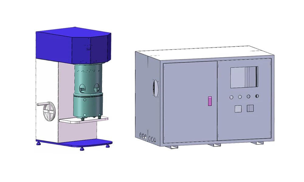
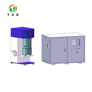
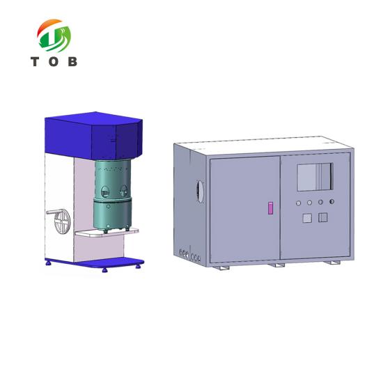
The two bodies of the machine as separate units: the cantilever mixing head with its manual lift handwheel and the vessel on its shelf, and to the right the independent control cabinet that stays outside the glovebox.
Electrical and Mechanical Components
The component list is short, which on a lab machine is a feature: fewer suppliers to chase when a part fails and a smaller set of spares to hold. The two items that decide how the machine behaves inside a box are the drive train and the seal, and both are named below.
| No. | Component | Brand |
|---|---|---|
| 1 | Motors | Inovance |
| 2 | Mixing gearbox and motor | Inovance |
| 3 | PLC | Delta |
| 4 | HMI touch screen | Weinview |
| 5 | Main electrical components | Schneider Electric, Huibang, Omron |
| 6 | Switching power supply | MEAN WELL |
| 7 | High speed bearings | NSK, Japan |
| 8 | Drive belt | Luodi |
| 9 | Gears | Shaoguan Gear |
| 10 | Vacuum pump | Tanshi or Feiyue |
Two rows carry more weight than the rest in a glovebox. The NSK bearings sit on the dispersion shaft, which is the only part of the machine doing 3850 rpm, and a bearing that starts to sing is the first sign that a shaft seal is about to be loaded sideways. The vacuum pump is the one component that lives outside the vessel but inside or beside the box depending on your layout, and its exhaust has to be routed out of the box rather than into it, because what it pulls off the slurry is solvent vapour. Neither point is in the datasheet, and both belong in the installation drawing.
Why a 2 L Planetary Mixer Belongs Inside the Glovebox
A glovebox is a controlled atmosphere with a small working volume, and every object that passes through its antechamber costs a purge cycle. That single fact explains most of the design decisions on this machine. If you mix outside the box, the slurry has to come in as a sealed container, be opened inside, be transferred to a coating or assembly step, and the empty container has to go back out. Each of those steps is an opportunity to admit moisture and oxygen into an atmosphere you have spent hours drying down, and the operator cannot see the contamination happen.
Mix inside the box and the batch never crosses the boundary. Powder goes in through the antechamber in a bottle, the vessel is charged, mixed and degassed in place, and the slurry goes straight to the next step in the same atmosphere. The machine stays inside permanently and only consumables cross the wall. This is why the machine is worth buying as a glovebox unit rather than as a standard bench mixer carried in on a trolley: the value is not in the mixing action, which is the same, it is in the fact that the mixing action can happen on the inside of the seal.
The planetary geometry is what makes that practical at 2 L. A single-shaft stirrer in a 180 mm vessel leaves a stagnant layer on the wall and a mound on the bottom, and on a bench the operator fixes both with a spatula. Inside a box the operator has three gloves and a restricted reach, and reaching into a vessel to scrape the wall is exactly the kind of thing that ends with slurry on a glove and atmosphere on the slurry. The PTFE wall scraper turns continuously with the planetary arm and does that job mechanically, and the two mixing shafts plus two dispersion shafts mean the whole 2 L is swept rather than stirred in the middle.
Vacuum is the third reason, and it is the one that changes when the vessel is inside a box. Degassing in a sealed vessel is always useful, because a slurry that is full of bubbles coats to a pinhole and a pinhole becomes a self-discharge site. What changes inside a box is where the gas goes. The pump pulls the foam down and exhausts the vapour, and if that exhaust is discharged into the box, the solvent you just removed goes into the atmosphere you were protecting. Route the exhaust outside and the vacuum system works for the box rather than against it. That is a plumbing decision, not a machine decision, but it is the one people forget.
Keeping the cabinet outside is the fourth. A variable frequency drive and a control transformer are the two warmest things in a mixing setup, and a sealed box has a finite cooling capacity, usually a water circuit and a small heat exchanger. Put the drives inside and the box spends part of that capacity on the machine's electronics instead of on the process, and the operator has to open a port to reach a screen that could have been on the outside. The split also means an electrical fault is fixed from outside the box, which is a maintenance argument as much as a thermal one.
What the machine does not do is make a box work. It does not dry your atmosphere, it does not remove solvent vapour that has already escaped, and it does not solve cleaning. Cleaning between batches is the least glamorous part of in-box mixing: the vessel and blades have to be cleaned without introducing a solvent load the purifier cannot handle, and that usually means a solvent that your own box specification already tolerates and a cleaning routine written before the first batch rather than after the first failure. Buy the machine for the mixing, plan the cleaning separately.
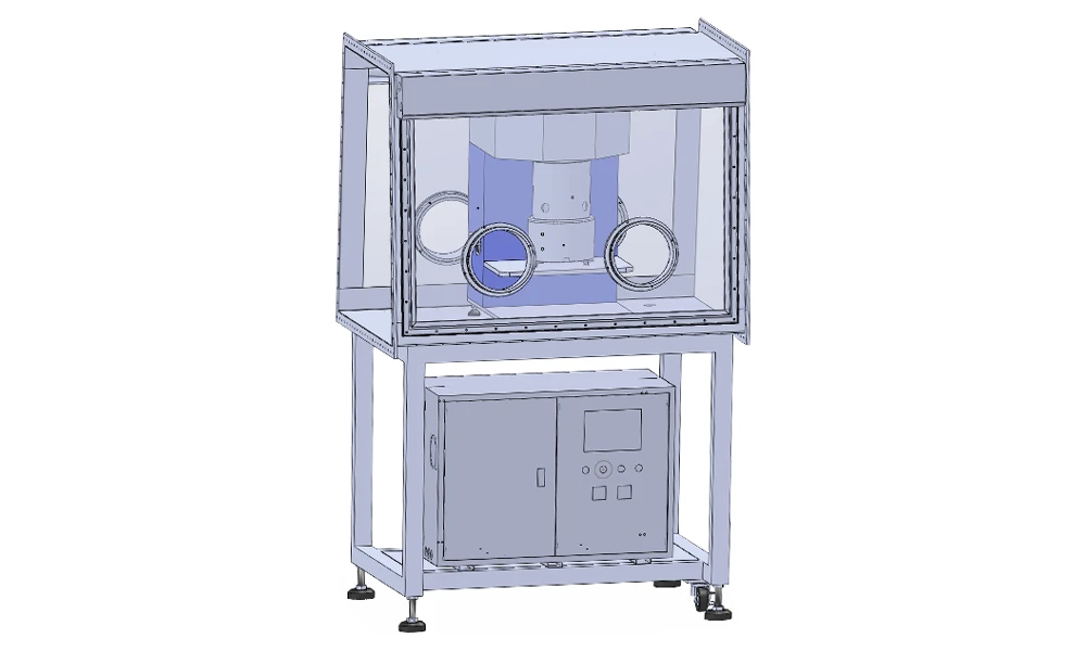
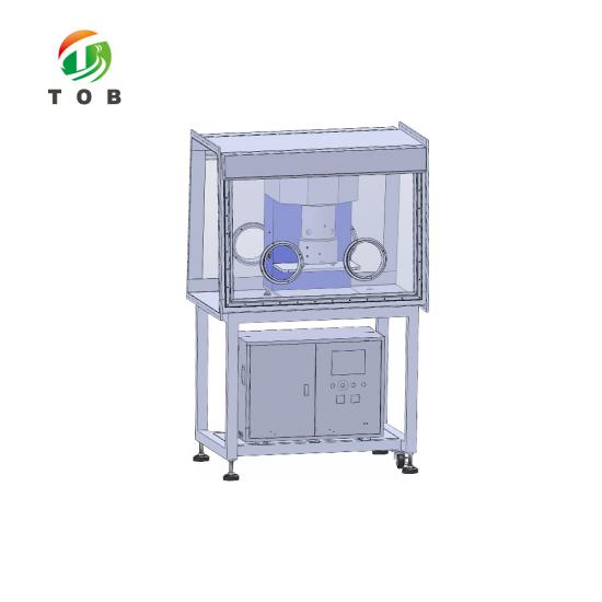
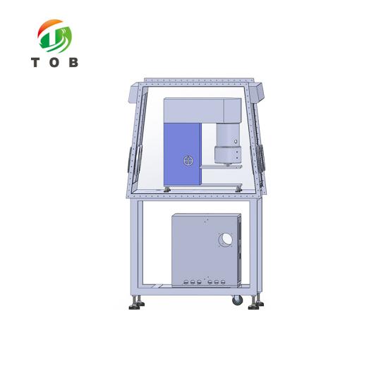
The working arrangement: mixing head and vessel inside the sealed box behind the glove ports, control cabinet on the frame below it, outside the atmosphere.
Key Engineering Characteristics
- Split head and cabinet. Only the mixing head and vessel enter the box, at 640 x 450 x 780 mm. The drives, the PLC, the HMI and their heat stay outside, which is the difference between a mixer that can live in a glovebox and one that merely fits in it.
- Manual lift, no compressed air. The head is raised by a handwheel on the column, and every valve on the machine is hand operated. Nothing pneumatic has to cross the box wall, so the wall keeps one penetration fewer and the atmosphere keeps one leak path fewer.
- Spotlight fitted to the head. A glovebox interior is dark, and the alternative to a light inside is opening the box to look. The light lets an operator watch the batch through the ports and the DN50 sight glasses with the seal intact.
- Water jacket rather than a refrigerant circuit. G1/2 in and out on a SUS304 jacket, with no insulation required by the datasheet. The utilities crossing the wall are then water, vacuum and power, and nothing else.
- Ceramic-faced dynamic seals. SiC-S against fluororubber on the rotating shafts, with silicone, fluororubber or nitrile statics. Under vacuum the shaft seal is the only path between the vessel and the box atmosphere, so it is the part that decides whether a leak costs you vacuum or costs you the batch.
- Cast and machined blades with stated clearances. The twisted frame blade is cast in one piece, then machined and polished, which is what makes 2 to 4 mm to the bottom, 2 to 5 mm to the wall and 3 to 10 mm blade to blade numbers you can inspect rather than a description of intent.
- 2 L effective inside a 3 L design volume. The two thirds fill ratio leaves room for the planetary arm to travel and for foam to rise before the vacuum collapses it. A vessel run to its design volume mixes at the wall and degasses badly, and no amount of vacuum time fixes it.
Operating Recommendations, Maintenance and Safety
1. Loading, Running and Unloading Inside the Box
Charge the vessel on its shelf with the head raised, then lower the head by handwheel until the lid seats on the vessel and the seal is compressed. Powder goes in through the DN50 quick-open inlet rather than by lifting the lid where possible, because every lid opening is a volume of box atmosphere exchanged with the vessel. Add liquid through the same opening, or through a port on the lid if your recipe needs the powder wetted first.
Start mixing only after the vessel is closed, which is enforced by the interlock rather than left to the operator. Run the recipe in stages: low-speed planetary rotation to wet out and homogenise, high-speed dispersion to break agglomerates, then vacuum at reduced speed to collapse the foam. Watch the two DN50 sight glasses rather than the clock, because the point at which the foam stops rising is a property of your slurry and not of the datasheet. Release the vacuum through the vent valve before raising the head; lifting a head off a vessel that is still under vacuum is how lids, gaskets and fingers get damaged.
2. Maintenance Items and Spares
The datasheet publishes no service intervals, and it would be wrong to invent them: the duty cycle of a glovebox mixer ranges from one batch a week to several a day, and the seal life follows the solvent and the solids, not the calendar. What can be said is the order in which things wear. The dynamic shaft seals go first, because they see both vacuum and rotation. The PTFE scraper blade goes next, since it is a soft material running against stainless. Then the drive belt, then the dispersion shaft bearings. Set your own intervals from your own duty and inspect in that order.
One maintenance point is specific to the installation rather than the machine: the vacuum pump. It sits outside the vessel and, depending on your layout, outside the box, and its exhaust must be piped away from the box rather than discharged into the room the box draws from. Service it on the pump maker's schedule and check the exhaust line for solvent condensate at the same time, because a blocked exhaust turns a vacuum problem into a solvent-in-the-box problem.
3. Safety Protection
- Emergency stop on the control panel, which stops the machine immediately when pressed
- Over-current and overload protection on the motors and on the variable frequency drives
- Mixing can only start once the upper and lower vessel bodies are closed, so the interlock, not the operator, protects the gap
The emergency stop is on the cabinet, which means it is outside the box. That is the right place for it and also the one ergonomic compromise of the split design: an operator standing at the glove ports has to step to the cabinet to hit it. If your risk assessment requires a stop within reach of the ports, a second station wired into the same circuit is the answer, and it is a change to quote with the order rather than to retrofit.
4. Standard Accessories and Documents
| Category | Item |
|---|---|
| Standard accessory | One set of seals for the vessel body and lid |
| Standard accessory | One set of drive belts |
| Standard accessory | One 5 m three-core power lead |
| Standard accessory | One manual scraper |
| Document | Operation manual |
| Document | Danfoss inverter manual |
| Document | Packing list |
Two of those items matter more than the rest for a glovebox installation. The spare seal set is worth having in the drawer before the first batch, because a leaking lid seal is the most common reason a vacuum mixer stops holding and the machine is unreachable while the box is open. The 5 m three-core lead is the supplied length for the run from the cabinet to the head; if your cabinet sits further from the box than that, say so with the order, because the lead is part of the standard supply rather than an accessory you would normally re-terminate in an inert-atmosphere lab.
Engineering FAQ
Q: Will it fit inside my glovebox?
The machine inside the box is 640 mm long, 450 mm wide and 780 mm high. The number that actually decides the answer is not 780 mm but 780 mm plus the lift stroke, because the head has to rise before the vessel can go in or come out, and the lift stroke is not published in the datasheet. Send us the interior clear height, the internal width and the position of the ports, and we will confirm the fit against the drawing rather than against the datasheet alone. If the box is short, the lift can be arranged differently, but that is a change to make before the order.
Q: Does the machine need compressed air or a gas line inside the box?
No. The lift is manual and every valve on the machine, including the vacuum valve and the vent valve, is hand operated. There is no pneumatic actuator and no air regulator in the supply. What crosses the wall is one single-phase power circuit, cooling water in and out, and the vacuum line, which is a short list and each item on it is a plain mechanical connection rather than a controlled one.
Q: Where does the vapour the vacuum pump pulls off the slurry go?
Out of the pump exhaust, which is why the exhaust has to be routed away from the box and not into the room the box draws its air from. What the pump removes is solvent vapour and air from the vessel, and discharging that inside a sealed box would put back part of what the vacuum was there to remove. Many installations put a cold trap or a condenser on the line ahead of the pump to keep solvent out of the pump oil; that is your call and your equipment, but the exhaust route is worth settling at the installation drawing stage.
Q: Can the control cabinet sit further away than the supplied lead?
The standard supply includes one 5 m three-core lead between the cabinet and the head, so a cabinet placed within that run needs nothing extra. If your layout puts the cabinet in a services corridor or on the far side of the box, tell us the distance with the order: the lead length is part of the build, and extending it afterwards means re-terminating a cable inside an inert-atmosphere laboratory, which is the kind of job that gets postponed.
Q: Is there a viscosity limit, and what batch size is realistic?
The datasheet does not publish a viscosity limit, so we will not invent one. What it does publish is the drive: 0.75 kW on the planetary shafts at up to 70 rpm rotation and 112 rpm shaft speed, and 1.5 kW on the dispersion shafts at up to 3850 rpm and 9.47 m/s tip speed. That is a high-shear dispersion drive on a 2 L batch, which is what lets the machine handle a solids-loaded slurry rather than a dilute one. The realistic batch is up to the 2 L effective volume, well short of the 3 L design volume, and if your formulation is unusually stiff the honest answer is to send a sample and let us run it rather than to compare power figures.
Q: Is the glovebox included?
No. The mixer is the machine; the box in the drawings is shown to explain the arrangement, and the frame in those drawings is part of the installation rather than of the mixer. If you need both, they are quoted as two items, and the box can be sized around the machine once the lift stroke and the cabinet position are fixed. Buying them together is easier than retrofitting a box around a machine that has already arrived.
One last thing worth knowing: nothing in the design requires the box. The machine runs as a bench mixer if your process is not confined to an inert atmosphere, and the split cabinet is then simply a convenience rather than a requirement. The glovebox is the reason this version exists, not a limitation on where it can be used.
Send us your glovebox interior drawing and the batch you want to run, and we will confirm the fit, the lift stroke and the cabinet position before the machine is built.
Email: tob.amy@tobmachine.com | Tel / WhatsApp: +86 181 2071 5609
Reviewed by: Science Wang, Six Sigma Black Belt, Battery Lines | Last updated: 2026-10-30
If you are interested in our products and want to know more details,please leave a message here,we will reply you as soon as we can.




 subscribe to us