Chinese
 français
 Deutsch
 italiano
 español
 português
 Nederlands
 日本語
 한국의




- Home
- >
- Battery Materials
- >
- Cathode Active Material
- >
- LMFP Cathode Electrode on Carbon Coated Aluminum Foil
Categories
Hot Products

Loading...
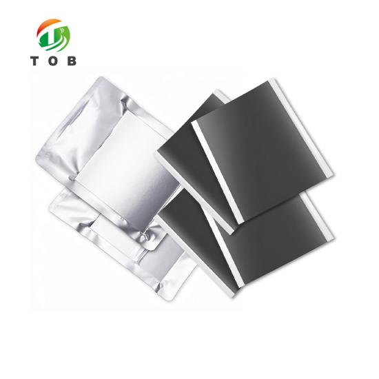
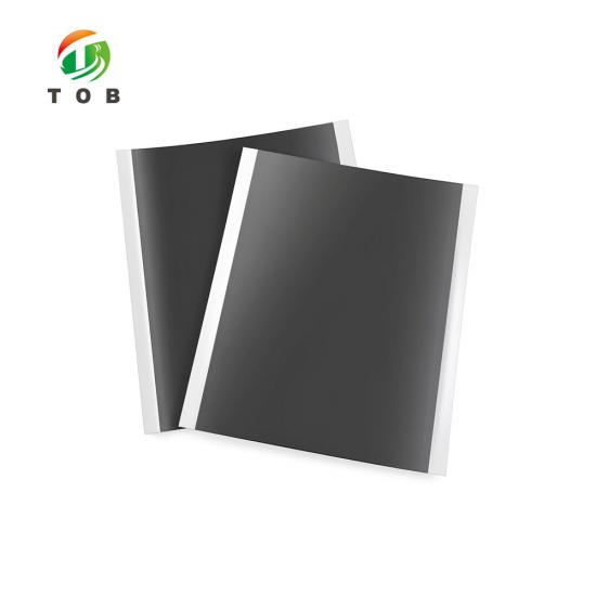
LMFP Cathode Electrode on Carbon Coated Aluminum Foil
Brand:
TOB NEW ENERGYitem no.:
TOB-CE-LMFP-D-180241order(moq):
1Payment:
L/C,T/Tproduct origin:
Chinashipping port:
XIAMEN
LMFP Cathode Electrode on Carbon Coated Aluminum Foil - TOB-CE-LMFP-D-180241
Double-sided calendered LMFP electrode, 241 x 180 mm, 28 mg/cm² on 15 μm carbon-coated foil, 5 sheets per vacuum pack
Product Overview and Ideal Applications
The TOB-CE-LMFP-D-180241 is a finished electrode, not a powder and not a slurry. Lithium manganese iron phosphate is coated on both faces of a 15 μm aluminum foil that already carries a 1 μm carbon layer on each side, and the coating is then calendered to a compacted density of 2.3 g/cm³. The sheet measures 241 mm long by 180 mm wide, but the coating is only 150 mm wide: a 15 mm strip of bare foil is left along each of the two long edges, so that the electrode can be welded, clamped or gripped without the tool ever touching active material.
The material itself is the reason this sheet exists. LMFP keeps the olivine phosphate structure that makes LFP safe and long-lived, and puts manganese into the lattice to raise the operating voltage. That is the commercial argument in one sentence: more energy per kilogram than LFP, without the thermal and cycle-life compromises of moving to a layered oxide. The trade-off is real, and it is what shapes the rest of this page. Olivine phosphates conduct electrons poorly, and they are hard to press to a high density, so both the substrate underneath the coating and the calendering step above it carry more of the performance than they would in an NMC electrode.
The reference values for cell design are 140 mAh/g over a 2.5 to 4.3 V window, with 94.90% of the coating mass being active material. Read those as reference values rather than guarantees: the capacity you actually obtain depends on your electrolyte, your formation protocol and the rate you test at. What the sheet fixes is the geometry and the loading, so that when you measure a difference downstream you can attribute it to your process rather than to an electrode that arrived slightly different from the last one.
Buyers use it in three ways. As a screening electrode when a new LMFP source or a new electrolyte has to be compared against a baseline, where a 5-sheet pack is enough to run a small design of experiments on coin cells. As a build electrode for a lab-scale pouch cell programme, where 241 x 180 mm is close to the format of a single-layer or few-layer cell. And as a reference in incoming inspection, where the same geometry is run against a supplier sheet on the same line so that only the material differs between the two arms of the test.
Ideal for:
- Coin cell screening of LMFP formulations, electrolytes and formation protocols on a fixed, known loading
- Single-layer and few-layer pouch cell builds that need a 241 x 180 mm electrode format
- Comparative trials of carbon-coated versus plain aluminum foil as a cathode substrate
- Calendering and lamination studies where 2.3 g/cm³ is the baseline to move away from
- Incoming inspection, where lot-to-lot comparison requires identical geometry between lots
This page covers the electrode only, and it is worth being explicit about the boundaries. If what you need is the active material, the LMFP cathode powder is a separate product supplied by weight, for buyers who coat their own foil. If your evaluation runs on coin cells, the route from cutting to test is covered by the coin cell lab line equipment; if you are building the pouch cell, the stations that match the process table further down are listed under the pouch cell assembly line. Solvent-free electrodes belong to a different family again, and the dry electrode film page is the closest reference point on this site. What this sheet cannot do is predict your cell result: it is one input to a process, and a 5-sheet pack is sized for evaluation, not for production.
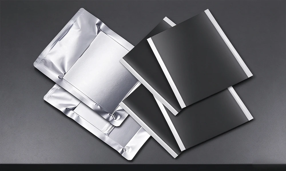
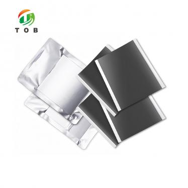
Three finished sheets beside two vacuum-sealed packs. The dark area is the calendered LMFP coating; the bright strips are the 15 mm bare-foil margins left along two edges.
Complete Specifications
The first table is the datasheet for this size, reproduced without rounding. Anything with a tolerance is written as the nominal by the tolerance, because on an electrode those two numbers are equally load-bearing: a sheet that hits 28 mg/cm² but lands at 2.5 g/cm³ is not the part you specified.
1. Electrode and Coating
| Item | Parameters |
|---|---|
| Electrode dimensions | 241 mm L x 180 mm W |
| Coated area dimensions | 241 mm L x 150 mm W (15 mm of white space on each side) |
| Coated side(s) | Double-sided coating (calendered) |
| Substrate dimensions | Aluminum foil 15 μm x 180 mm; double-sided carbon layer 1 μm x 150 mm |
| Coating areal density | 28 ± 0.4 mg/cm² |
| Foil areal density | 4.09 mg/cm² |
| Compacted density | 2.3 ± 0.1 g/cm³ |
| Active material mass fraction | 94.90% |
| Reference specific capacity | 140 mAh/g |
| Reference voltage range | 2.5 to 4.3 V |
| Active material mass calculation | Coating areal density x active material content x electrode dimensions |
Two rows in that table are easy to read past, and both change what the sheet can be used for. The substrate row is two numbers, not one: a 15 μm foil 180 mm wide, and a 1 μm carbon layer that only covers the 150 mm coated width. The remaining 15 mm on each side is plain aluminum, which is exactly what a tab weld wants. The last row is a formula rather than a value, and the third subsection below works it through in full.
2. Packaging, Storage and Other Sizes
| Item | Parameters |
|---|---|
| Standard size | 241 mm L x 180 mm W, coated area 241 mm L x 150 mm W |
| Packing | 5 sheets per vacuum-sealed pack |
| Other sizes | Made to order: length, width, coated width and margin |
| Storage after opening | Seal and store; a 60 °C oven or a glovebox is acceptable |
Once a pack is opened, the sheets will pick up moisture from the air, and a dried electrode is the difference between a coating that adheres and one that blisters after electrolyte filling. The datasheet note is deliberately short: seal the sheets again after opening, and store them either in a 60 °C oven or in a glovebox. Either is acceptable, but pick one and keep to it, because the two give you different surface states and switching between them mid-programme introduces a variable you did not intend to test.
Other sizes are made to order, and it is worth knowing which of the numbers are easy to change and which are not. Length and width follow the cutting die. The coated width and the 15 mm margin follow the coating head, so a different margin is a different coating run rather than a trimming step. The loading, 28 mg/cm², follows the coating gap and the solids content. If you need a small change, say which edge the margin should be on, because a 15 mm margin on two edges and a 15 mm margin on one edge are not the same part when the sheet reaches the stacking fixture.
3. Active Material Mass, Cell Capacity and Thickness
Everything in this subsection is arithmetic on the table above. None of it is an additional datasheet value, and none of it should be quoted to a customer as a measured result. The point is to let you size a test before the sheets arrive.
Capacity per side = specific capacity x coated area x coating areal density x active material fraction. The area that belongs in that formula is the coated area, 241 mm x 150 mm, and not the full electrode, because the uncoated margins carry no active material at all.
| Quantity | Calculation | Result |
|---|---|---|
| Full electrode area | 241 mm x 180 mm | 433.80 cm² |
| Coated area, one side | 241 mm x 150 mm | 361.50 cm² |
| Coating mass, one side | 28 mg/cm² x 361.50 cm² | 10.12 g |
| Active material, one side | 10.12 g x 94.90% | 9.61 g |
| Capacity, one side | 140 mAh/g x 9.61 g | 1.345 Ah |
| Capacity, both sides | 2 x 1.345 Ah | 2.69 Ah |
| Coating thickness, one side | 28 mg/cm² ÷ 2.3 g/cm³ | about 122 μm |
| Electrode thickness, total | 15 μm foil + 2 x 1 μm carbon + 2 x 122 μm coating | about 261 μm |
| Sheet mass, foil plus coating | 4.09 mg/cm² x 433.80 cm² + 2 x 10.12 g | about 22 g |
Three assumptions sit behind those numbers, and you should agree with all three before you put any of them in a proposal:
- 28 mg/cm² is the loading on each face. That is the usual datasheet convention for a double-sided electrode. If your supplier means the two faces combined, halve every mass and capacity figure in the table.
- The coated area carries the active material. Run the same arithmetic on the full electrode area of 433.80 cm² and every figure inflates by 20%, because 180 mm divided by 150 mm is 1.2 and the difference is bare foil.
- The carbon layer is outside the sheet mass. The datasheet does not weigh the 1 μm layers separately, so the 22 g figure covers foil plus the two coatings only.
The tolerances are worth carrying through as well. A tolerance of ±0.4 mg/cm² on 28 mg/cm² is ±1.4%, which is ±38 mAh on a 2.69 Ah double-sided sheet, or roughly one and a half percent of the cell. The ±0.1 g/cm³ on compacted density does not change the mass, but it moves the per-side thickness between about 117 μm and 127 μm, so a stack height you calculate from the nominal 122 μm can be out by 10 μm per sheet before anything has gone wrong.
The values in subsection 3 are derived from the datasheet by the formulas shown. They are not separate measured specifications and they carry the tolerances above.
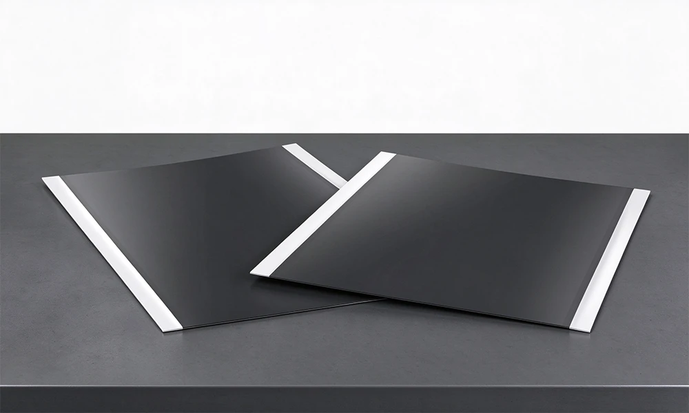
The two bright strips on each sheet are the 15 mm margins, one along each long edge. Both the coating and the 1 μm carbon layer stop at the 150 mm coated width, so what is visible there is bare aluminum foil.
Reference Process for Double-Sided Electrode Pouch Cells
The route below is the reference sequence TOB quotes for turning this sheet into a double-sided electrode pouch cell. The equipment column names the station that performs each step, and every one of those models is a catalogue item rather than a placeholder. The parameters are reference setpoints to plan against, not a validated recipe: your electrolyte, your separator and your cell format will move the baking times and the formation current, and they should.
1. The Reference Route, Station by Station
| Process Flow | Supporting Equipment | Reference Parameters |
|---|---|---|
| Cell Capacity Setting | / | Specific capacity x electrode area x coating areal density x active material content |
| Electrode Sheet Punching & Cutting | TOB-MQ300 | Die-cut positive and negative electrode sheets to fixed dimensions |
| Electrode Sheet Stacking | TOB-BDP200-C | Stack electrode sheets according to the design |
| Hot Pressing & Micro-short Circuit Test | TOB-HS-2681 | Hot pressing: 2 min at 45 °C |
| Tab Welding | TOB-USW-800W | Weld aluminum tabs to the positive electrode and nickel tabs to the negative electrode |
| Aluminum-Plastic Film Forming | TOB-SCK200 | Form (deep-draw) aluminum-plastic film to the appropriate depth and dimensions |
| Cell Top & Side Sealing | TOB-SFZ-200 | Pouch cell pre-treatment |
| Cell Baking | TOB-DZF-6050 | 80 °C for 12 hours |
| Electrolyte Filling | TOB-ZYB-01 | Inject a specific amount of electrolyte |
| Vacuum Pre-sealing | TOB-YF200-JZ | Pre-seal the pouch cell |
| Internal Resistance Test | TOB-HP3560 | Test cell voltage and internal resistance |
| Cell Aging | TOB-DZF-6050 | 45 °C for 12 hours |
| Cell Formation | TOB-CT-4008Q-5V6A-S1 | Low-current formation |
| Cell Aging | TOB-DZF-6050 | 45 °C for 12 hours |
| Final Cell Sealing | TOB-BFZ-200 | Evacuate internal gas and vacuum seal |
| Internal Resistance Test | TOB-HP3560 | Test voltage and internal resistance |
| Cell Capacity Grading | TOB-CT-4008Q-5V6A-S1 | Determine capacity |
Read the first row as the link back to the previous section. Cell capacity setting has no equipment against it because it is a calculation: specific capacity x electrode area x coating areal density x active material content, which is the formula worked through above. Everything downstream of that number, from the amount of electrolyte injected to the grading window, scales with it, so an error in the loading assumption propagates all the way to the last station.
2. The Assembly Half of the Route as a Flowchart
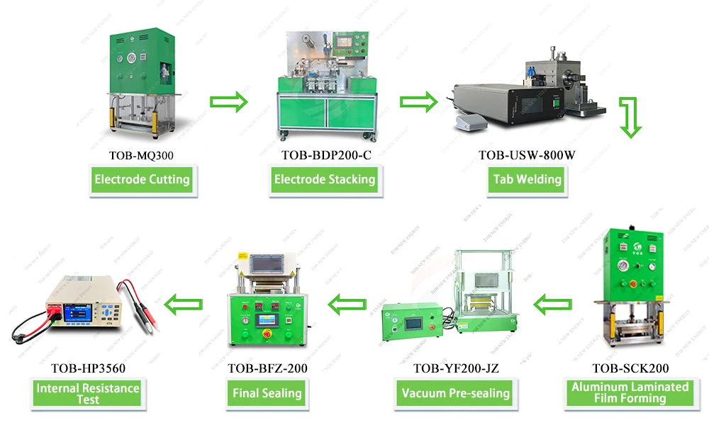
Seven stations of the pouch cell route: TOB-MQ300 electrode cutting, TOB-BDP200-C electrode stacking, TOB-USW-800W tab welding, TOB-SCK200 aluminum laminated film forming, TOB-YF200-JZ vacuum pre-sealing, TOB-BFZ-200 final sealing and TOB-HP3560 internal resistance test.
The flowchart is not the whole table, and it is worth seeing which part it covers. It runs from cutting to the resistance test after final sealing, that is the geometry and sealing half of the route. Baking, electrolyte filling, aging and formation sit between vacuum pre-sealing and final sealing in the table, and they are process steps in ovens and glovebox equipment rather than stations on this assembly loop, which is why they do not appear as a box.
3. Screening the Electrode on Coin Cells First
Most buyers do not start with the pouch cell. They start with a coin cell, because a coin cell answers the question the electrode was bought to answer, which is whether this LMFP lot and this electrolyte give the capacity and the first-cycle efficiency that the datasheet implies, and it answers it with a few square centimetres of material per cell instead of a full 241 x 180 mm sheet. The 5-sheet pack then covers a small matrix of formulations rather than a single build.
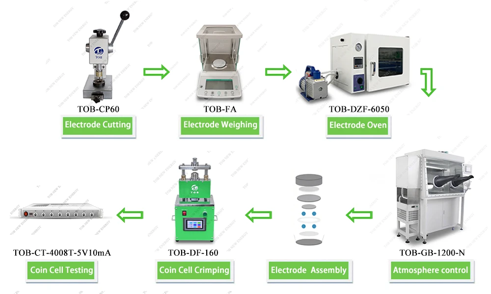
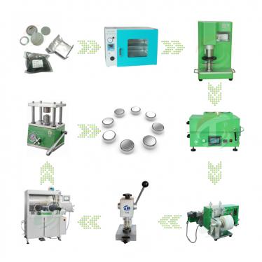
The coin cell route in seven stations: TOB-CP60 electrode cutting, TOB-FA electrode weighing, TOB-DZF-6050 electrode oven, TOB-GB-1200-N atmosphere control, electrode assembly, TOB-DF-160 coin cell crimping and TOB-CT-4008T-5V10mA coin cell testing.
Two stations in that flowchart are the ones that decide whether your numbers mean anything. The weighing station is where the loading of the punched disc is checked, because a 12 mm disc cut from a sheet with a ±0.4 mg/cm² tolerance does not have the same active mass as the next disc, and capacity per gram only compares across cells if the mass is known. The atmosphere station is where the electrode is kept dry between the oven and the crimping, and that is the same moisture problem the storage note in the specification table is about, moved into the glovebox.
Why the Carbon Layer and the Calender Both Matter on This Electrode
Start with what is under the coating. Aluminum is a good collector and a poor interface: it passivates in air within seconds, and the oxide that forms is resistive. A 1 μm carbon layer on each face replaces that oxide with a conductive, slightly rough surface that is stable against the electrolyte. On an NMC electrode the coating would still work, but you could argue about whether it earns its place. On an olivine phosphate you cannot: LMFP conducts electrons far less well than a layered oxide, so the interface resistance is a much larger share of the total cell resistance, and every milliohm at the foil is worth more here than it is elsewhere in the cell.
The carbon layer also does a mechanical job that the electrical argument tends to hide. At 28 mg/cm² the coating is roughly 122 μm thick on each side, which is a thick electrode by lab standards, and a thick coating is held onto the foil by the binder alone unless there is something for it to key into. The roughness of the carbon layer is that something. Take it away and the failure mode is not a gradual loss of performance, it is delamination: a sheet that looks perfect in the bag and sheds coating at the margin after it has been punched, stacked and handled. Nothing downstream recovers from that.
Calendering is the other half of the same trade. Pressing the coating raises the volumetric energy density and improves particle-to-particle contact, and both of those show up immediately in the numbers. It also closes porosity, and porosity is the space the electrolyte has to fill and the space lithium ions have to move through. Whether 2.3 g/cm³ is the right point on that curve depends on the rate you need, and that is a decision for your cell design rather than for the electrode supplier. What the sheet does is hold the value within ±0.1 g/cm³, so that when you move it you are moving it deliberately and can attribute the result to the change.
The 94.90% active material fraction is the third lever, and it is the one buyers read least carefully. The remaining 5.10% is binder and conductive additive, and that is the budget from which both adhesion and the electronic network inside the coating are paid. A higher active fraction gives more capacity for the same mass; it also leaves less room for the carbon black network that carries electrons to the foil, which is precisely the weakness of the chemistry. 94.90% is a compromise figure, and it is quoted to two decimal places because it enters every capacity calculation you will run on this sheet.
The 15 mm margins deserve a paragraph of their own because they are the part of the design that fails first in production. The positive tab is ultrasonically welded to the electrode, and ultrasonic welding needs clean metal: put the horn on coating and the weld nugget picks up active material and binder, which is a weak joint and a contamination source inside the pouch. The same strip is what the gripper holds when the sheet is transferred from the punch to the stacker. A margin that is wide enough for the tab but not for the gripper still gives you a handling problem, which is why the margin is specified as a coating parameter and not left to the cutting die.
What none of this fixes is the cell. The 140 mAh/g reference figure in the table is quoted without a rate against it, so treat it as a comparison point between lots measured the same way rather than as an absolute you can drop into a specification. The same applies to the 2.5 to 4.3 V window: it is a reference range for design, and the upper cut-off you actually use is a life decision before it is a capacity decision. The electrode is a well controlled input; the output is still your process.
Key Engineering Characteristics
- Loading and density are two separate promises. 28 ± 0.4 mg/cm² and 2.3 ± 0.1 g/cm³ are independent numbers, and a sheet can meet one while missing the other. Both appear as tolerances in the datasheet so that both can be checked on arrival rather than inferred from cell results three weeks later.
- Both faces are coated and calendered. This is a double-sided electrode in the finished sense, not a single-sided sheet coated twice. The 122 μm per-side figure and the 261 μm stack height in the calculation table both assume the two faces are symmetric, so if you measure one face only, fold the result into the total rather than into a single-sided comparison.
- The carbon layer stops at the coated width. 1 μm on each face, over 150 mm, inside a 180 mm foil. The 15 mm outside that is bare aluminum, and that boundary is a feature of the part, not an artefact of the coating run.
- Two bare margins, one along each long edge. They are the tab weld zone and the gripper zone. On a custom size, say which edge the margin belongs to: two margins and one margin are different parts in the stacking fixture.
- 94.90% active material fraction, quoted to two decimals. It is not decoration. It multiplies directly into the active material mass and therefore into the capacity of every cell you build from the sheet, and a one percent error in it moves a 2.69 Ah electrode by about 27 mAh.
- Five sheets to a vacuum pack. The pack size is an evaluation quantity: enough for a coin cell matrix or a few single-layer pouch cells, not enough to fill a production line, and it keeps the opened quantity small enough to store properly.
- Other sizes made to order. Length and width follow the die; coated width and margin follow the coating head; loading follows the coating gap and the solids content. Changing the margin is a new coating run, not a trimming step, and it should be quoted as one.
Handling, Storage and Safety
1. Storage Once the Pack Is Opened
The datasheet note is short and it is the whole storage specification: seal the sheets again after opening, and store them in a 60 °C oven or in a glovebox. Both are acceptable, and the choice is yours, but make it once. An electrode dried in an oven and an electrode held in a glovebox arrive at the stacker with different surface states, and a programme that switches between the two halfway through has introduced a variable that will be very hard to separate from the chemistry later.
What the note is protecting against is moisture, and the failure it prevents is not subtle. Water taken up by the coating comes off again during vacuum drying and pre-sealing, and at best it costs you pump time; at worst it reaches the electrolyte, where it hydrolyses the salt and produces hydrogen fluoride. That is a first-cycle efficiency and a gas problem, and it will be blamed on the material unless the storage step is controlled. Keep opened sheets in their sealed pack until the moment of use, and do not leave a part-used pack sitting in the open laboratory between shifts.
2. Handling the Sheet
Handle the sheet by the bare margins. They exist for the tooling, and they are also the only part of the electrode that tolerates fingers, powder-free gloves or tweezers without leaving something behind on the active area. Once a sheet has been gripped across the coating, the mark is there for the life of the cell, and on a 122 μm coating it is also a crack initiation point.
Avoid bending or creasing the coated area, and do not let two sheets slide against each other. Coating-on-coating abrasion looks harmless on a bench and shows up later as pinholes and as micro-short failures at the hot-pressing and micro-short circuit station in the process table. If sheets have to be transported loose, interleave them rather than stacking them bare. Cutting and punching should stay inside the design outline, and trimming into the margin is a change to the part rather than a tidy-up.
3. Safety
This is an electrode, not a cell. It holds no charge, contains no lithium metal and no electrolyte, and it has no voltage across it, so the electrical hazards people associate with battery work do not apply at this stage. The hazards that do apply are the ordinary ones of a fine powder bonded into a coating: dust from cutting, punching or trimming should be extracted at the tool rather than swept up afterwards, and offcuts should go into your normal electrode scrap stream under your own site rules rather than into general waste.
Solvent and binder residues are the other consideration, and they belong to your coating supplier's data rather than to this page. If your EHS function needs a classification for transport or for storage, ask for it with the order so that the paperwork travels with the goods rather than being reconstructed after they arrive.
Engineering FAQ
Q: Can you supply a different size?
Yes. The 241 x 180 mm size is a stocked format, not the only one. Send the electrode length and width, the coated width, which edges should carry the margin, whether the sheet is single or double sided, and the loading you want, and the quotation will come back against those numbers. Be specific about the margin, because it is set by the coating head and not by the die, and a margin change quoted as a trimming operation will come back as a different coating run.
Q: Is 28 mg/cm² the loading on each side, or for both sides together?
It is quoted per side in the datasheet as supplied, which is the usual convention for a double-sided electrode. It is worth confirming on the purchase order anyway, because the difference is a factor of two on every mass and capacity figure: at 28 mg/cm² per side the sheet carries about 2.69 Ah, and if the figure were the two faces combined it would carry about 1.35 Ah. The calculation table in the specification section works from the per-side reading and shows which lines to halve.
Q: Can this sheet be used in a cylindrical cell?
Not as supplied. It is a flat, cut sheet with the bare margins running along the two long edges, which is a stacked-cell layout. A wound design needs the uncoated margin to run along the winding direction and needs a narrow strip rather than a 180 mm wide sheet, and at 122 μm per side the coating is stiff enough that tight winding radii bring their own cracking risk. Tell us the cell format before you design around this electrode and we will quote a slit or a differently margined sheet instead.
Q: What does the carbon layer actually contribute, and is it included in the foil areal density?
The layer lowers the resistance between the coating and the foil and gives the binder something to key into, which is what keeps a 122 μm coating attached through punching and stacking. It does not add capacity. As for the 4.09 mg/cm² in the table: 15 μm of aluminum at 2.7 g/cm³ works out at 4.05 mg/cm², so that row is consistent with the foil alone, and the 1 μm carbon layer is not separately accounted for in it.
Q: Does the pack come with lot-specific test data?
The datasheet on this page is the specification for the part. If your incoming inspection needs measured values for the delivered lot, agree the measurements and the test method before the order is placed, so that they can be written into it. Asking after the goods have shipped is the one route that reliably does not work, because the only remaining option is to measure the sheets you have already opened.
Q: Is 60 °C the operating temperature of this electrode?
No. The 60 °C in the datasheet is a storage and drying allowance for the sheet, not a thermal rating, and it should not be carried into a cell specification as one. The only electrical reference on this page is the 2.5 to 4.3 V window, which is a design range for the cell rather than a limit of the electrode on its own.
If your question is about a size, a loading or a margin that is not on this page, it is probably faster to ask than to work around it. Custom runs are how most of these electrodes are actually sold.
Tell us the cell format you are building and the loading you need, and we will confirm the electrode size, the margin layout and the packing before anything is coated.
Email: tob.amy@tobmachine.com | Tel / WhatsApp: +86 181 2071 5609
Reviewed by: Science Wang, Six Sigma Black Belt, Battery Lines | Last updated: 2026-10-30
Previous:
Battery Cathode Active Materials NMC LFP NCA LNMO Batch OrderNext:
MnO₂ Electrode for Zinc-Manganese Batteries
If you are interested in our products and want to know more details,please leave a message here,we will reply you as soon as we can.

 subscribe to us