Chinese
 français
 Deutsch
 italiano
 español
 português
 Nederlands
 日本語
日本語 한국의
한국의




- Home
- >
- Batteries for Sale
- >
- Sodium-ion Batteries
- >
- 15Ah 3.85V Anode-Free Pouch Cell
Categories
Hot Products
Loading...
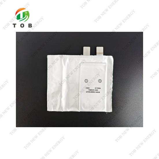
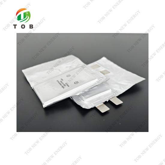
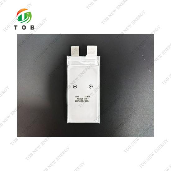
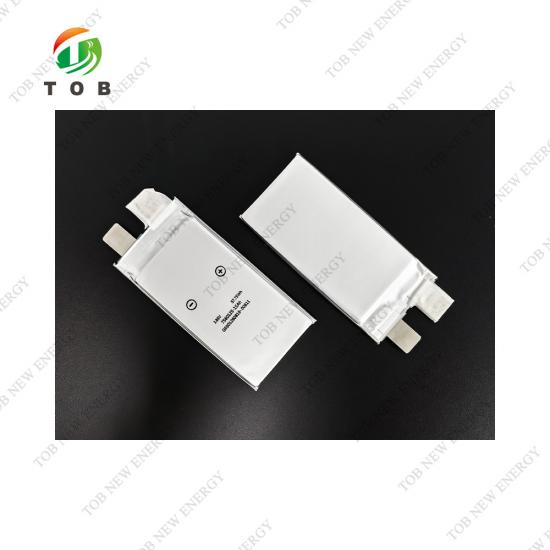
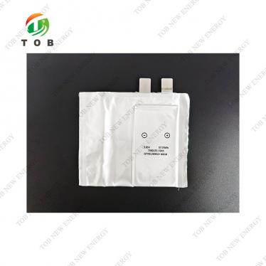
15Ah 3.85V Anode-Free Pouch Cell
Brand:
TOB NEW ENERGYitem no.:
TOB-AF-15AH-1060125order(moq):
1Payment:
L/C, T/Tproduct origin:
Chinashipping port:
XIAMEN
15Ah 3.85V Anode-Free Pouch Cell | TOB-AF-15AH-1060125
Product Overview
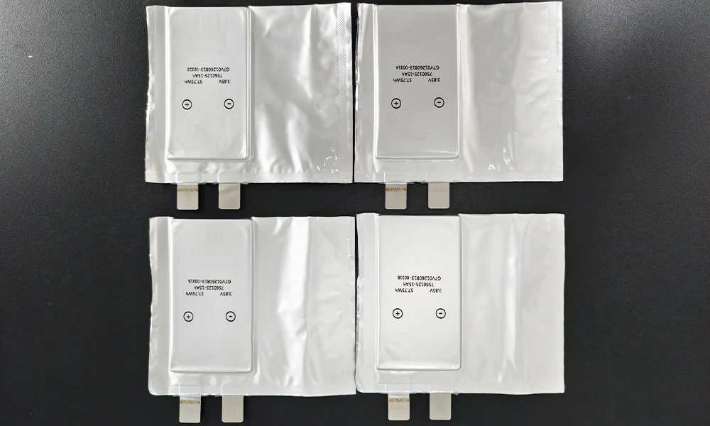
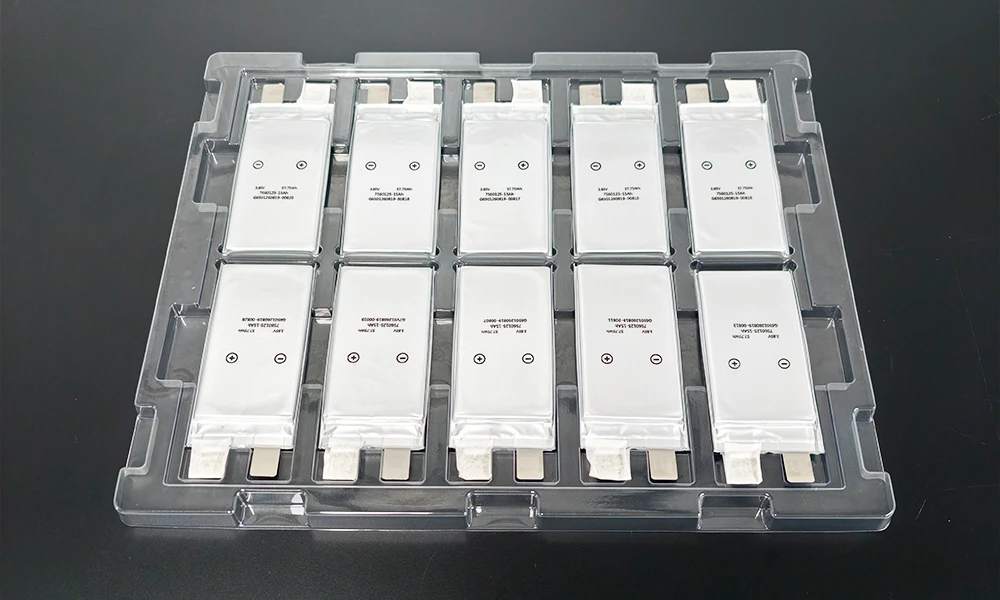
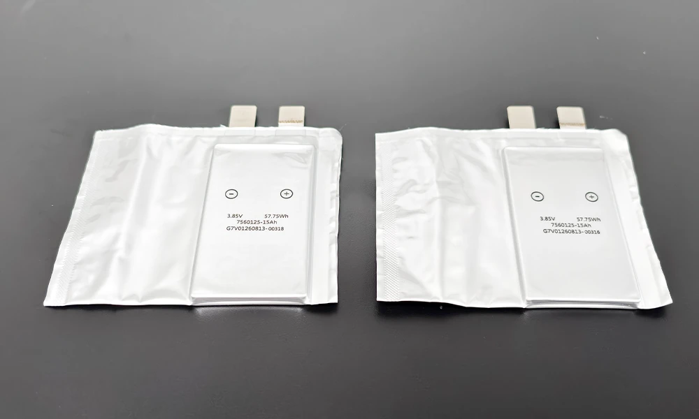
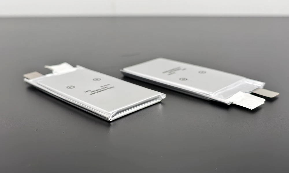
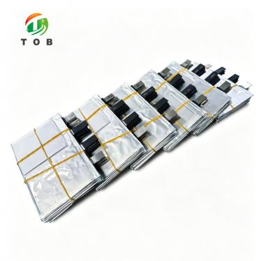
The 15Ah 3.85V Anode-Free Pouch Cell is a high-performance pouch-type battery cell developed for advanced battery research, cell development, and electrochemical performance evaluation. The cell adopts an anode-free architecture and aluminum-plastic film packaging, providing a compact and lightweight cell format for laboratory and pilot-scale battery development.
With a nominal capacity of 15 Ah and a nominal voltage of 3.85 V, the cell operates within a voltage range of 3.0–4.3 V under specified temperature conditions. Its maximum continuous discharge capability reaches 8C, while the maximum pulse discharge capability reaches 15C for up to 10 seconds at 50% SOC.
The cell measures approximately 8.0 × 60 × 125 mm and weighs 137 ± 10 g (dimensions measured under a compression force of 150–200 N, per the cell drawing). Its compact pouch-cell configuration makes it suitable for battery research programs requiring anode-free cell architectures, high-power performance evaluation, and controlled cell-level testing.
Key Features
- 15 Ah nominal capacity
- 3.85 V nominal voltage
- Anode-free pouch cell architecture
- Aluminum-plastic film pouch packaging
- 3.0–4.3 V operating voltage range under specified conditions
- ≤ 2 mΩ AC internal resistance at 1 kHz under specified test conditions
- 8C maximum continuous discharge current
- 15C maximum pulse discharge current for 10 seconds
- 4.3 V maximum charging voltage
- Compact 8.0 × 60 × 125 mm cell format
- Lightweight design with a nominal weight of approximately 137 g
- Suitable for advanced battery research and cell development
Applications
The anode-free pouch cell is suitable for a range of advanced battery research and development applications, including:
- Anode-free battery research
- Advanced lithium battery development
- Pouch cell research and development
- High-power battery cell evaluation
- Battery electrochemical performance testing
- Battery material and cell architecture research
- Laboratory-scale battery development
- Pilot-scale battery development
- Cell-level charge and discharge testing
Cell Construction
- The cell uses aluminum-plastic film as the external pouch packaging material. Its compact pouch-cell structure is designed for controlled laboratory and development-stage testing.
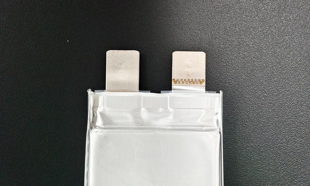
- The cell dimensions are approximately 8.0 mm in thickness, 60 mm in width, and 125 mm in height, measured under a compression force of 150–200 N as specified in the cell drawing. The pouch cell is equipped with battery tabs with a tab width of 15 ± 1 mm, a tab length of 18 ± 2 mm, and a center-to-center tab spacing of 30 ± 1.5 mm.
Electrical Performance
- The cell has a nominal capacity of 15 Ah and a nominal voltage of 3.85 V. Under the specified test conditions, the cell supports a maximum continuous discharge rate of 8C and a maximum pulse discharge rate of 15C for 10 seconds at 50% SOC.
- The standard charging current is 0.1C, with a maximum continuous charging current of 0.2C. The standard charging voltage is 4.3 V.
- The standard discharge current is 0.1C. The discharge cut-off voltage is 3.0 V when the cell temperature is ≥ 0 °C and 2.4 V when the cell temperature is below 0 °C.
Thermal Operating Conditions
- The recommended charging temperature is 15–35 °C, while the recommended discharge temperature is 10–35 °C.
- The absolute charging temperature range is 0–45 °C, and the absolute discharge temperature range is −20–45 °C. Charging or discharging should be stopped when the cell temperature exceeds the specified absolute operating limits.
- For storage, the recommended temperature range is −20–45 °C under an ambient relative humidity of ≤ 70 % RH.
Charging Conditions
- Under standard charging conditions, the cell is charged at 0.1C constant current at 25 ± 2 °C until the cell voltage reaches 4.3 V. Constant-voltage charging is then maintained at 4.3 V until the charging current decreases to 0.05C.
- The maximum charging voltage is 4.3 V. Charging should be stopped if the cell voltage exceeds the specified absolute charging voltage limit or if the cell temperature falls outside the specified absolute charging temperature range.
Discharging Conditions
- Under standard discharge conditions, the cell is discharged at 0.1C constant current at 25 ± 2 °C until the cell reaches the specified discharge cut-off voltage.
- The maximum continuous discharge rate is 8C at 25 ± 2 °C. For pulse discharge applications, the cell supports up to 15C for 10 seconds at 50% SOC under the specified test conditions.
Internal Resistance
- The cell has an AC internal resistance of ≤ 2 mΩ under the specified measurement conditions: 10 ± 5% SOC, 25 ± 2 °C, and AC measurement at 1 kHz.
- Internal resistance may vary depending on cell temperature, SOC, measurement method, and test equipment. Therefore, resistance values should be evaluated under consistent test conditions when comparing cell performance.
Cycle Life
- The specified cycle life is ≥ 25 cycles under the stated test conditions, using 0.2C charging and 8C discharge with a cell pre-tightening pressure of 0.2 MPa.
- This figure is a research-stage benchmark measured under an intentionally aggressive high-rate protocol (0.2C charge / 8C discharge) on an anode-free architecture, in which the finite lithium inventory is plated and stripped in-situ. Actual cycle performance may vary depending on operating temperature, charge/discharge protocol, applied pressure, SOC window, equipment, and other test conditions. Cycle life under moderate discharge rates (e.g., 0.5C–1C) should be established separately under your target protocol.
Shipping Condition
- The specified shipping voltage range is 3.0–4.1 V, with a target shipping SOC of 10 ± 5% under 25 ± 2 °C conditions.
- The cell should be handled, transported, stored, charged, and discharged according to the applicable battery safety and transportation requirements.
Technical Specifications
General Specifications
| Item | Product Specification | Remark |
| Rated Capacity | 15 Ah | 0.1C discharge, new cell |
| Nominal Voltage | 3.85 V | 0.1C discharge, new cell |
| Working Voltage | 3.0–4.3 V | Cell temperature ≥ −0 °C |
| 2.4–4.3 V | Cell temperature < −0 °C | |
| Battery Internal Resistance | ≤ 2 mΩ | 10 ± 5 % SOC, new cell, AC 1 kHz, 25 ± 2 °C |
| Battery Dimensions | 8.0 × 60 × 125 mm | 150 N–200 N, refer to cell drawing |
| Battery Weight | 137 ± 10 g | N.A. |
| Shipping State | 3.0 V – 4.1 V | 10 ± 5 % SOC, 25 ± 2 °C |
| Cycle Life | ≥ 25 | 0.2C charge / 8C discharge cycle (preload force: 0.2 MPa) |
| Optimal Charge Working Temperature | 15–+35 °C | |
| Optimal Discharge Working Temperature | 10–+35 °C | |
| Storage Temperature | −20–+45 °C | Ambient humidity ≤ 70 % RH |
Charge Specifications
| Item | Specification | Remark |
| Standard Charge Current | 0.1C | 25 ± 2 °C |
| Max. Continuous Charge Current | 0.2C | 25 ± 2 °C |
| Standard Charge Voltage | 4.3 V | Maximum voltage of a single cell |
| Standard Charge Mode | 25 ± 2 °C; constant-current charge at 0.1C to the maximum single-cell voltage of 4.3 V, then constant-voltage charge at 4.3 V until the current drops to 0.05C | |
| Standard Charge Temperature | 25 ± 2 °C | Cell temperature |
| Absolute Charge Temperature (cell temperature) | 0–+45 °C | Regardless of the charge mode, charging is stopped once the cell temperature exceeds the absolute charge temperature range |
| Absolute Charge Voltage | Max. 4.3 V | Regardless of the charge mode, charging is stopped once the cell voltage exceeds the absolute charge voltage range |
Discharge Specifications
| Item | Specification | Remark |
| Standard Discharge Current | 0.1C | 25 ± 2 °C |
| Max. Continuous Discharge Current | 8C | 25 ± 2 °C |
| Max. Pulse Discharge Current | 15C | 25 ± 2 °C, 10 s, 50 % SOC |
| Discharge Cut-off Voltage | 3.0 V | Cell temperature ≥ 0 °C |
| 2.4 V | Cell temperature < 0 °C | |
| Standard Discharge Mode | 25 ± 2 °C, constant-current discharge at 0.1C to the single-cell cut-off voltage of 3.0 V | |
| Standard Discharge Temperature | 25 ± 2 °C | Cell temperature |
| Absolute Discharge Temperature | −20–+45 °C | Regardless of continuous or pulse discharge mode, discharge is stopped if the cell temperature exceeds the absolute discharge temperature |
Dimensional Specifications
| Item | Description | Standard Dimension | Unit | Remark |
| L | Cell height | 125 ± 2 | mm | |
| W | Cell width | 60 ± 2 | mm | Side folded |
| W1 | Tab width | 15 ± 1 | mm | |
| L2 | Tab length | 18 ± 2 | mm | |
| M | Tab center distance | 30 ± 1.5 | mm | |
| T | Cell thickness | 8.0 ± 1.5 | mm | |
| L1 | Tab glue exposure | > 0 | mm |
Cell dimensions are measured under a compression force of 150–200 N, per the cell drawing.
Engineering FAQ
Q1: What does "anode-free" mean in this cell?
In an anode-free cell, there is no pre-formed anode active layer (no graphite or silicon) at assembly. On the first charge, lithium from the cathode plates in-situ onto the bare anode current collector as metallic lithium. This removes the anode active material and its weight, which is the source of the anode-free architecture's energy-density advantage, at the cost of requiring precise control of plating conditions.
Q2: Is this cell a "dry cell" in the conventional sense?
No. The term "dry cell" conventionally refers to Leclanché-type (carbon-zinc) primary batteries. This product is a pouch-format rechargeable cell for research use; the "anode-free" designation refers to its cell architecture, not to any dry-battery classification. When referring to this product in English, use "anode-free pouch cell," not "dry cell."
Q3: Why is the cycle life specified as ≥ 25 cycles, and why is a 0.2 MPa preload required?
The ≥ 25 cycle figure is measured under an aggressive 0.2C-charge / 8C-discharge protocol. Anode-free cells depend on uniform in-situ lithium plating, which is promoted by a controlled stack preload of 0.2 MPa. Both the preload and the low charge currents (0.1C standard, 0.2C maximum) are integral to the cell's operating conditions, protecting the limited lithium inventory and plating uniformity.
Q4: Why are charge currents limited to 0.1C–0.2C while discharge can reach 8C–15C?
High charge currents cause non-uniform, dendritic lithium plating in anode-free cells, which consumes the finite lithium inventory and risks internal shorts. Plating is therefore deliberately slow. Discharge (stripping) is less problematic, enabling the aggressive 8C continuous and 15C pulse discharge ratings.
Q5: What test fixture is recommended for this cell?
A fixture that applies a uniform 0.2 MPa stack preload across the cell face, with insulating, dust-free contact surfaces and allowance for the 8.0 ± 1.5 mm thickness tolerance. Given the 8C–15C discharge capability, a battery cycler with adequate current range and safety monitoring is required. Contact TOB for guidance on matching a cycler and fixture to this cell.
Product Summary
The 15Ah 3.85V Anode-Free Pouch Cell combines an anode-free cell architecture with a compact aluminum-plastic film pouch format. With a 15 Ah nominal capacity, 3.85 V nominal voltage, 8C continuous discharge capability, and 15C pulse discharge capability, it provides a practical cell platform for advanced battery research and development.
For detailed technical specifications, dimensional drawings, testing conditions, or application requirements, please contact our technical team.
tob.amy@tobmachine.com | +86 181 2071 5609
You May Also Need
▶ 1Ah NFM Sodium-Ion Pouch Cell for Research — A research-grade sodium-ion pouch cell for comparative studies across emerging battery chemistries.
▶ Custom Lithium-Ion Batteries for Sale — Custom lithium-ion battery cells tailored to specific form factors and performance requirements.
▶ Sodium-Ion 73174207 Prismatic Cell for Sale — A prismatic sodium-ion cell for evaluating alternative chemistries alongside anode-free lithium technology.
Previous:
Sodium ion 73174207 Prismatic Cell for SaleNext:
1Ah NFM Sodium-Ion Pouch Cell for Research
If you are interested in our products and want to know more details,please leave a message here,we will reply you as soon as we can.

 subscribe to us