Chinese
 français
 Deutsch
 italiano
 español
 português
 Nederlands
 日本語
日本語 한국의
한국의




- Home
- >
- Battery Production Line
- >
- Cylindrical Cell Production Line
- >
- 4680 4690 Tabless Battery Cylindrical Cell Production Line
Categories
Hot Products
Loading...
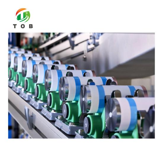
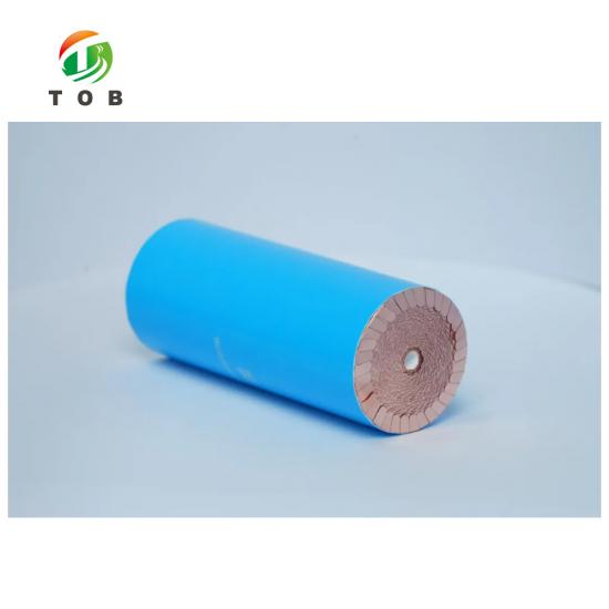
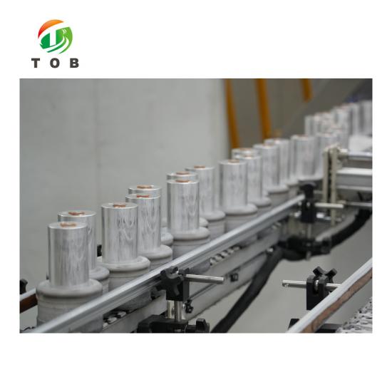
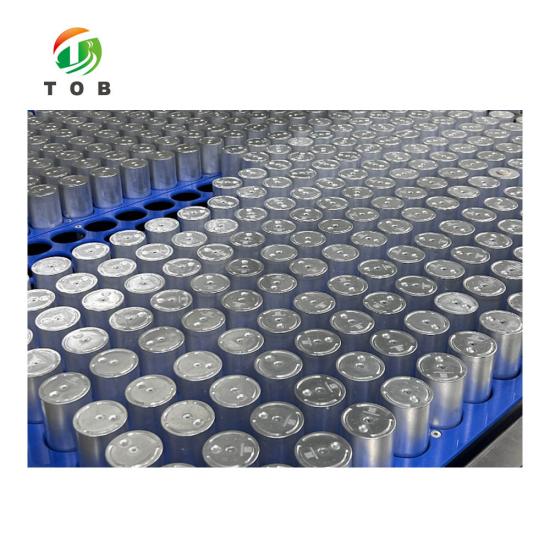
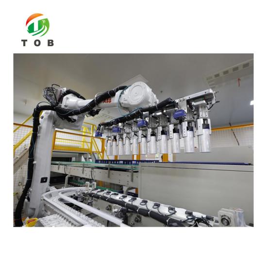
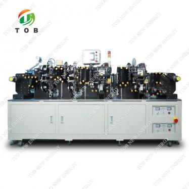
4680 4690 Tabless Battery Cylindrical Cell Production Line
Brand:
TOB NEW ENERGYitem no.:
TOB-4680PLorder(moq):
1 setPayment:
L/C,T/Tproduct origin:
Chinashipping port:
XIAMENLead Time:
30-180days
4680 / 4690 Tabless Cylindrical Battery Cell Production Line Solution
Product Overview
The TOB-4680PL is TOB's turnkey production line solution for 4680 / 4690 tabless cylindrical lithium-ion cells. It covers the complete manufacturing chain from electrode processing through cell assembly, electrolyte filling, formation, and final grading and testing — and it is delivered together with the battery materials required to run the line, so a single supplier is accountable for both the machines and the consumables.
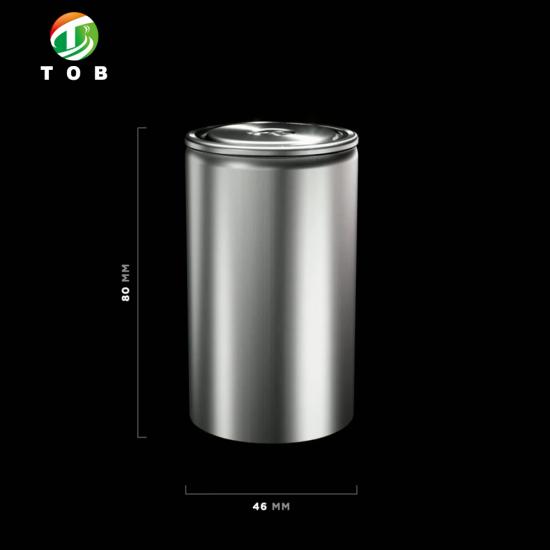
The 4680 and 4690 formats are large-format cylindrical cells with a 46 mm diameter; the 4680 has an 80 mm height and the 4690 has a 90 mm height. Compared with the conventional 18650 or 21700 format, a large 46 mm cell holds far more active material per unit, which reduces the number of cells and electrical interconnects in a finished pack, simplifies pack architecture, and lowers pack-level cost — the driving force behind the format's rapid adoption in electric vehicles and large-scale energy storage.
The technology at the heart of the line is the tabless (full-tab) architecture. In a conventional cylindrical cell, current is collected through small discrete tabs welded to the electrode foils, which concentrates current into a few narrow points and limits the cell's power capability. In a tabless cell, the uncoated foil edges run across the full electrode height and are exposed as a continuous fringe at both ends of the jelly roll; the collector disc is welded to this complete annular fringe, so the entire circumference collects current. For a large-format cell, where the current per cell is high and the foil path is long, the tabless architecture lowers internal resistance, distributes current uniformly, reduces heat generation, and enables the fast charging and high continuous discharge rates that 4680-class applications require.
TOB has focused on 4680 / 4690 tabless technology and supplies both the production machinery and the battery cell materials for the format. The TOB-4680PL is engineered, configured, and accepted as a complete production solution: scope, capacity, station parameters, site utilities, acceptance criteria, and service terms are all defined in a single engineering proposal.
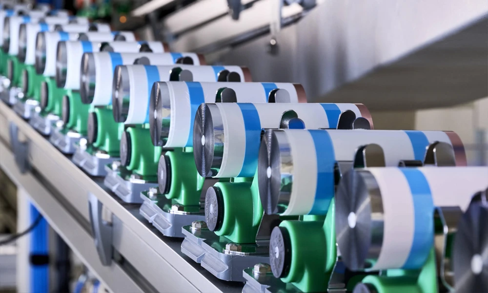
Tabless Technology: Why the 4680 / 4690 Format Uses It
A conventional cylindrical cell conducts its entire current through a small number of tabs welded to the electrode foils. This tab bottleneck concentrates current into narrow points, raises local resistance and heat, and caps the cell's continuous discharge rate. The larger the cell, the worse the bottleneck becomes — which is why the tabless construction is fundamental to the 46 mm format rather than an optional refinement.
In a tabless cell:
- The uncoated edge of each electrode extends across the full electrode height, forming a continuous exposed foil fringe at both ends of the wound jelly roll.
- A collector disc is welded to the full annular fringe at each end, so current is collected around the entire circumference instead of through discrete tabs.
- The current path is shortened and distributed evenly, which lowers DC/internal resistance, reduces current crowding and localized heating, and supports high-rate charging and discharge.
For the customer, this translates directly into cell performance: higher sustained power output, flatter voltage curves under load, less heat to manage at the pack level, and better suitability for fast-charging pack designs. For the manufacturer, it translates into three process stations that define the line: electrode edge cleaning, tabless winding, and collector-disc laser welding — supported by jelly-roll flattening for the large-diameter roll.
Line Process and Functional Modules
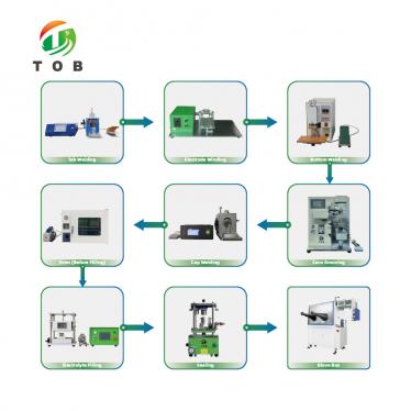
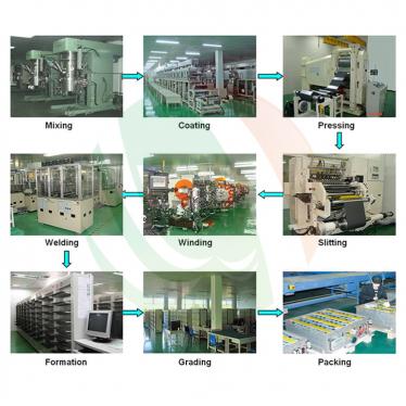
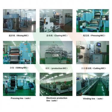
The TOB-4680PL is organized into three process stages, described below in process order.
Stage 1 — Electrode Manufacturing Section
1. Mixing
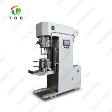
Cathode and anode slurries are prepared in high-shear mixers. Large-format cells use high areal loadings, so mixing must achieve complete dispersion of active material, conductive additive, and binder at high solid content with tight viscosity control.
2. Coating
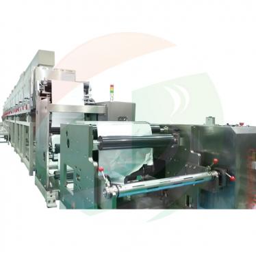
Slurries are applied to aluminium (cathode) and copper (anode) foil by coating equipment such as slot-die or transfer coaters, by multi-zone drying. Coating weight uniformity across the web is directly inherited by the finished cell as capacity consistency.
3. Calendering (Roller Press)
The dried electrode webs are compacted by precision roller presses to the target electrode density. Calendering also establishes the electrode's mechanical integrity, which matters because the large jelly roll is wound and flattened under tension downstream.
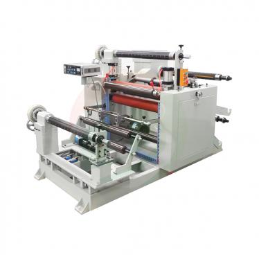
4. Slitting
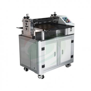
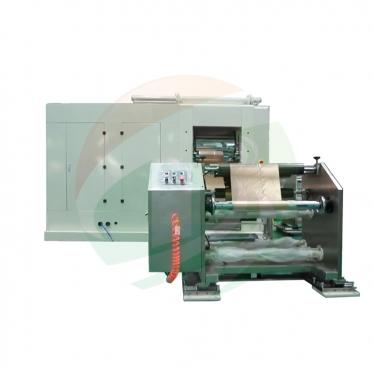
The calendered webs are slit to the exact electrode widths of the 4680 / 4690 jelly-roll design. Slit-edge quality (burr control) is the first line of defence against internal short circuits.
5. Electrode Edge Cleaning (Tabless-Specific)
The coating is selectively removed from the electrode edges — by laser ablation or mechanical cleaning — to expose bare, oxide-free foil over a defined width along the entire electrode length. This exposed foil becomes the current-collecting fringe welded to the collector disc. The process must remove the coating completely without thinning or pitting the 6–15 µm foil.
Stage 2 — Cell Assembly Section
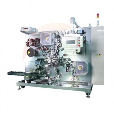
6. Tabless Winding
Cathode, separator, and anode strips are wound into the large jelly roll. The exposed foil edges must form an even fringe at both roll ends, with the foil distributed regularly around the circumference, because this fringe geometry determines the quality of the collector weld. Winding tension and edge alignment are controlled accordingly.
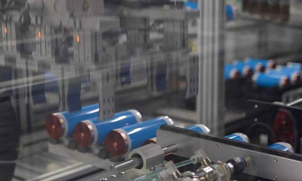
7. Jelly-Roll Flattening (Tabless-Specific)
The wound roll is flattened (pre-compacted) to a controlled profile before insertion into the can. Flattening stabilizes the foil fringe for welding, improves the fit of the roll inside the 46 mm can, and reduces the internal stress the roll exerts on the can wall.
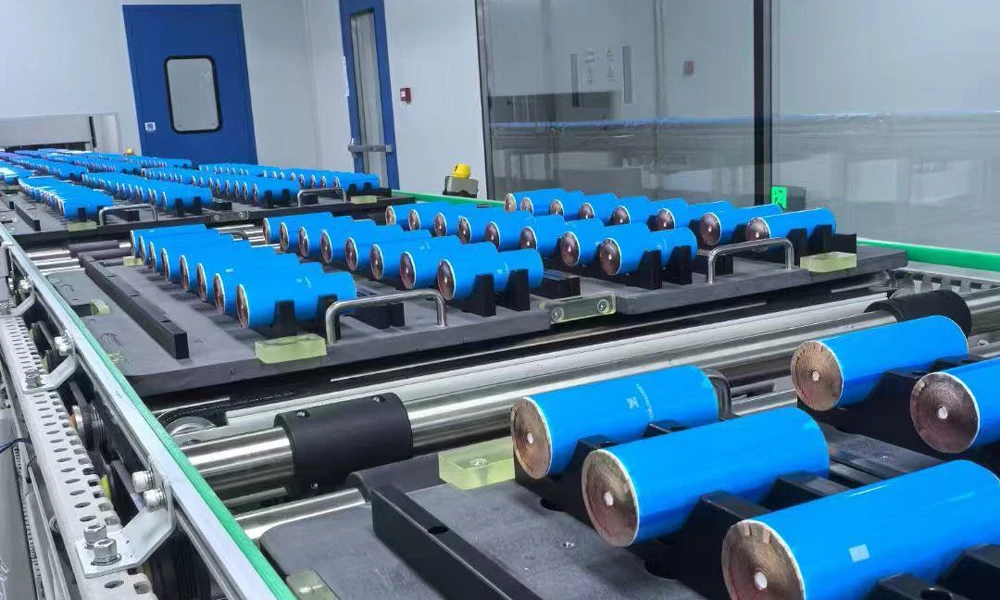
8. Current-Collector Laser Welding (Tabless-Specific)
The defining station of the tabless line. A positive collector disc is laser-welded to the exposed cathode fringe at one end of the roll, and a negative collector disc to the anode fringe at the other end. The weld must join the full annular fringe to the disc with low, uniform electrical resistance and without burning through the foil. Closed-loop weld monitoring and 100 % weld inspection verify that every cell's high-current path is complete.
9. Case Insertion and Insulation
The welded jelly roll is inserted into the 4680 / 4690 cylindrical can (steel or aluminium), with insulation components isolating the electrodes from the can and cap.
10. Top Cap Welding / Sealing
The cap — carrying the current-interrupt device (CID) and vent — is laser-welded to the can to complete the hermetic enclosure. Seal integrity is verified against the leak-rate specification.
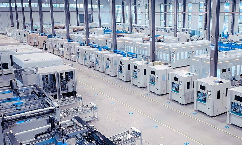
11. Electrolyte Filling
Electrolyte is introduced under vacuum to ensure complete wetting of the large, high-loading jelly roll. Filling parameters are engineered specifically for the 4680 / 4690 stack, which holds a considerably larger electrolyte volume than a small cylindrical cell.
Stage 3 — Formation, Grading, and Testing Section
12. Formation
The filled cells undergo controlled first charge-discharge cycles to form the SEI. The low-resistance tabless structure supports uniform current distribution during formation, and the formation station manages the heat generated by the large cell mass.
13. Degassing and Sealing
Gases generated during formation are removed, and the cell is sealed to complete its hermetic closure for service life.
14. Grading and Testing
Each finished cell is capacity-graded and its ACIR / DCIR, OCV, and other electrical parameters are measured, with cells sorted into defined bins. Grading output provides the per-cell data required for traceability and for downstream pack matching.
Station Parameter Framework
The following table defines the specification dimensions that are fixed for each station at the engineering-proposal stage, according to the selected cell design and line configuration. Numeric values are inserted into this framework during project engineering and confirmed in the equipment technical agreement.
| Process Section | Station | Specification Dimensions Defined per Project |
| Electrode | Mixing | Batch size, solid content range, viscosity control, vacuum level |
| Electrode | Coating | Coating method, coating width, coating speed, wet/dry thickness, weight tolerance |
| Electrode | Calendering | Roll width, line pressure, calendering speed, thickness accuracy |
| Electrode | Slitting | Slitting width range, width accuracy, burr control standard |
| Electrode | Edge Cleaning | Cleaning width, cleaning method, foil thickness compatibility, edge quality |
| Assembly | Tabless Winding | Cell format, winding tension control, edge alignment accuracy, cycle time |
| Assembly | Jelly-Roll Flattening | Roll profile control, flattening force, thickness control |
| Assembly | Collector Laser Welding | Laser power, welding speed, weld seam control, weld resistance criterion |
| Assembly | Case Insertion & Sealing | Can compatibility, insertion precision, seal weld parameters, leak-rate criterion |
| Assembly | Electrolyte Filling | Fill volume accuracy, vacuum level, cycle time |
| Formation / Grading | Formation & Grading | Channel count, current/voltage ranges, current/voltage accuracy, energy feedback efficiency, grading methods |
| Grading / Test | Battery Testing | Test parameters (capacity, ACIR/DCIR, OCV), test speed, data output |
Reference for planning: formation and grading equipment in this class typically provides an energy-feedback efficiency above 65 % (measured at rated conditions). Final values are confirmed per configuration.
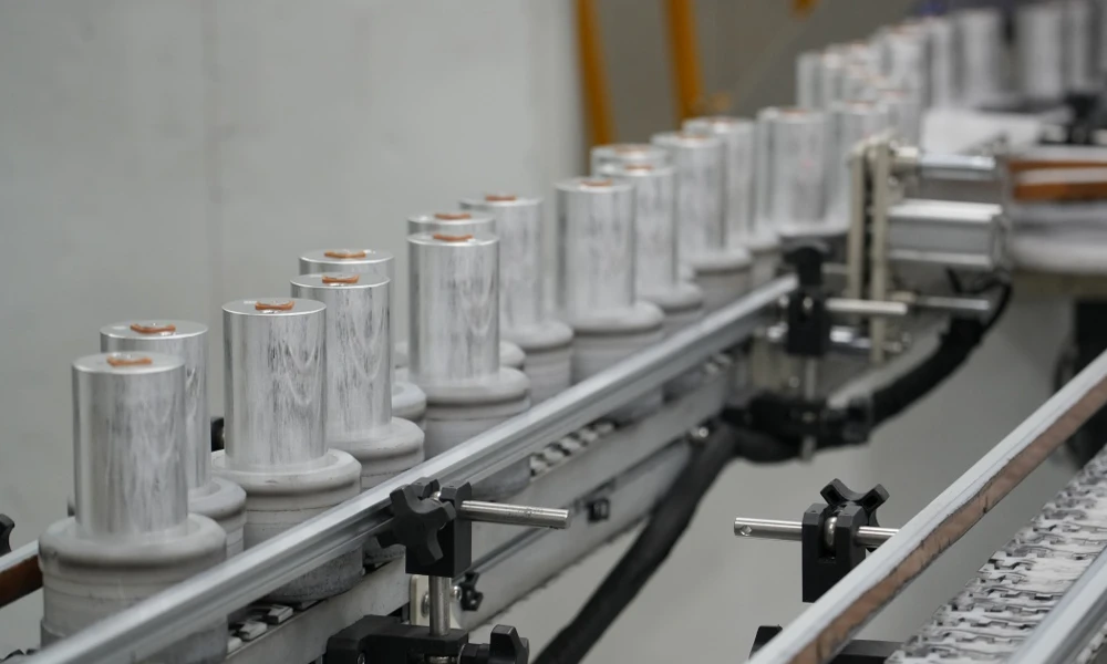
Site Utilities and Facility Requirements
A 4680 / 4690 production line is a complete manufacturing facility, not a standalone machine. The following utility and facility dimensions are engineered per site during project planning, and a site-preparation guide is provided to the customer before installation.
| Item | Requirement Dimension (defined per project) | Notes |
| Power supply | Total installed power, voltage class, distribution design | Defined by line configuration and station count; includes formation/grading load |
| Compressed air | Pressure, flow, dew point, oil-free requirement | Per station pneumatic demand |
| Nitrogen | Purity, pressure, flow | For moisture-sensitive steps |
| Vacuum | Vacuum level, flow, for filling and process stations | Per station design |
| Cooling | Cooling water / chilled water temperature, flow, pressure | For coating, welding, and formation equipment |
| Dry room (assembly) | Dew point, temperature, humidity control zone | Reference: moisture-sensitive assembly typically requires dew point ≤ −40 °C; final value per cell chemistry and process |
| Cleanliness | Cleanliness class per section | Defined per process sensitivity |
| Building | Floor area, clear height, floor loading capacity | Per line layout drawing |
| Exhaust & environment | Exhaust air volume, solvent (NMP) recovery, waste treatment | Compliant with local environmental requirements |
| Logistics | Material flow, aisle width, material handling interfaces | Per layout design |
Capacity, Yield, and Reliability Targets
Production targets for the TOB-4680PL are defined in the equipment technical agreement. The framework below shows the target dimensions and reference planning ranges.
| Item | Target Dimension | Reference / Status |
| Assembly section output | Cells per minute (PPM) | Reference planning range: 2–8 cells/min, depending on configuration |
| Annual design capacity | Cells per year | Reference planning range: approx. 0.8–3 million cells/year at 80 % OEE, 330-day calendar |
| Electrode section | Matched to assembly consumption | Sized to the assembly throughput |
| OEE target | % | Reference target: 80 % [To be confirmed by TOB engineering] |
| Yield (by section and overall) | % | Committed values defined at engineering-proposal stage [To be confirmed] |
| MTBF / MTTR | h / min | Committed values defined at engineering-proposal stage [To be confirmed] |
| Energy feedback efficiency (formation/grading) | % | Reference: > 65 % at rated conditions; final value per configuration |
All committed values are fixed in the equipment technical agreement before contract signature.
Project Delivery: Timeline, FAT / SAT, and Acceptance
A production line is delivered as a project with defined milestones. The structure below follows TOB's standard project process; durations are indicative for planning and are confirmed in the contract.
| Phase | Content | Timeline Status |
| 1. Requirement & design | Cell design input, line scope, 3D design review | Indicative; confirmed per project |
| 2. Manufacturing | Equipment manufacture, subsystem testing | Indicative; confirmed per project |
| 3. Pre-acceptance (FAT) | Factory acceptance testing against the FAT checklist; verification of key accuracy on site | FAT performed before shipment |
| 4. Shipment | Packing, shipping, customs | Per contract terms |
| 5. Installation & commissioning | On-site installation, commissioning, utility connection verification | Manpower and duration defined in the project plan |
| 6. Trial production | Small-batch trial run; approval of trial output before mass production | Per acceptance plan |
| 7. Formal acceptance | Continuous operation meeting technical-agreement requirements; acceptance data based on consecutive production data | Acceptance criteria per the equipment technical agreement |
| 8. Warranty period | Warranty support and service | 12 months from formal acceptance (standard; final terms per contract) |
Acceptance framework: Acceptance is performed against the equipment technical agreement, the FAT checklist, and TOB's standard project acceptance requirements (TPM requirements, 5S acceptance, general EHS requirements, and TECSA requirements). Formal acceptance is initiated after the line has operated continuously and met the specified technical indicators; the acceptance result takes effect upon signature by both parties. A warranty acceptance review is conducted based on the operational status of the month preceding warranty expiration.
Service, Warranty, and Training
- Warranty: 12 months from the date of passing formal acceptance. During the warranty period, TOB is responsible for repair and maintenance and for replacement of all components (excluding consumables); malfunctions caused by human factors or force majeure are excluded. (Standard terms; final terms are defined in the contract.)
- Response time: After-sales service personnel respond within 2 hours after receiving notification.
- After warranty: TOB continues to provide repair and maintenance support, charging reasonable labour and transportation fees; replacement parts are charged at parts cost.
- Training: TOB provides training to the customer's personnel covering normal operation, maintenance, fault analysis and troubleshooting, operational safety, and emergency handling procedures. The training scope and schedule are defined in the project plan.
- Documentation: Equipment certificate of conformity, operation manual, maintenance manual, spare-parts list, general assembly drawing, and pneumatic/electrical schematics are provided as part of delivery.
Intelligence, Data Traceability, and MES Integration
Modern 4680-class factories require cell-level traceability and process-data integration. The TOB-4680PL supports the following capabilities on configuration:
- Cell-level traceability: Barcode / QR binding at cell level, with process and test data linked to each cell identity, supporting forward and backward traceability.
- MES / SCADA integration: Data upload via industry-standard interfaces (e.g., Web/API) for integration with the factory MES; interface specification defined during project engineering.
- Process data management: Recipe management, measurement-result logging, alarm and event history, and statistical process analysis (SPC).
- Formation / grading data: Per-channel charge-discharge curves, capacity grading results, and internal-resistance data, with export formats for analysis and archiving.
- Energy monitoring: Recording of charge/discharge energy and energy-feedback data from the formation and grading section.
The final data-integration scope is defined with the customer's IT/MES requirements during project planning.
Battery Materials Supplied with the Line
TOB supplies the battery materials required to run the 4680 / 4690 line, so that process and material are co-optimised and the customer has a single accountable supplier for both.
| Material | Role in the 4680 / 4690 Cell |
| Cathode material | Cathode active materials for the high-energy, high-rate positive electrode |
| Anode material | Anode active materials for the negative electrode |
| Current collector | Aluminium foil (cathode) and copper foil (anode) for the large-format electrode |
| Separator | Separator membrane for the large jelly roll, engineered for winding and safety |
| Electrolyte | Electrolyte formulation matched to the cell chemistry and formation process |
| 4680 cell cans |
Bitmap Cylindrical can hardware for 4680-format cells — 4680 Cell Cans Materials Cylindrical can hardware for 4680-format cells — 4680 Cell Cans Materials
|
Engineering & Business FAQ
Q1: What does "tabless" mean, and why does the 4680 format need it?
A tabless cell uses the full uncoated edge of the electrode foils as its current-collecting path instead of discrete tabs. The collector disc is welded to the complete foil fringe at each end of the jelly roll, so current is collected around the entire circumference. In a large-format cell the current per cell is high and the foil path is long; discrete tabs would concentrate the current into narrow points, causing high local resistance and heat. The tabless architecture distributes current uniformly, lowers internal resistance, and enables the high charge and discharge rates the format is specified for.
Q2: What is the difference between the 4680 and the 4690 format?
Both are cylindrical cells with a 46 mm diameter; the 4680 is 80 mm in height and the 4690 is 90 mm. The taller 4690 accommodates a taller jelly roll and therefore a higher capacity per cell. The TOB-4680PL handles both formats — winding, flattening, and welding stations are configured to the cell design specified at order.
Q3: What is the scope of the TOB-4680PL?
The scope covers the electrode manufacturing section (mixing, coating, calendering, slitting, tabless edge cleaning), the cell assembly section (tabless winding, jelly-roll flattening, collector laser welding, case insertion, cap welding, electrolyte filling), and the formation / grading / testing section. The matching battery materials are supplied with the line.
The exact equipment set is fixed in the engineering proposal.
Q4: What capacity can the line be configured for?
The line is engineered to the buyer's target output. A typical configuration is designed for 2–8 cells per minute at the assembly section (approximately 0.8–3 million cells per year at 80 % OEE on a 330-day calendar); the electrode section is matched to this throughput. Committed capacity is fixed in the equipment technical agreement.
Q5: What site conditions must be prepared before installation?
The line requires power, compressed air, nitrogen, vacuum, cooling, and — for the assembly section — a controlled dry-room environment. A site-preparation guide covering power capacity, gas and cooling requirements, dry-room specification, building dimensions, floor loading, and logistics is provided during project planning, and the final values are defined in the engineering proposal.
Q6: How is the project delivered and accepted?
The project follows a defined sequence: design review, manufacturing, factory pre-acceptance (FAT), shipment, installation and commissioning, trial production, formal acceptance, and warranty. Acceptance is performed against the equipment technical agreement and TOB's standard acceptance framework (FAT checklist, TPM requirements, 5S acceptance, EHS, and TECSA requirements). Formal acceptance is based on continuous operation meeting the specified technical indicators.
Q7: What are the warranty and service terms?
The standard warranty is 12 months from formal acceptance, covering repair, maintenance, and replacement of components (excluding consumables). After-sales service responds within 2 hours of notification. Training for operation, maintenance, and troubleshooting is provided. Final terms are defined in the contract.
Q8: Can TOB supply the battery materials as well as the machinery?
Yes. TOB supplies the cathode material, anode material, current collector foils, separator, electrolyte, and the 4680 cell can hardware alongside the production line, so that process and material are co-optimised and the customer has a single supplier accountable for both.
Q9: Can the line be upgraded later, for example toward dry-electrode processing?
The line is designed with modular stations and defined interfaces, and TOB supplies complementary dry-electrode process equipment (film forming and transfer lamination) for manufacturers targeting solvent-free electrode production. Upgrade paths and interface compatibility are discussed during configuration planning.
Q10: What certifications apply?
TOB operates a certified quality and environmental management system (ISO 9001, IATF 16949, ISO 14001, ISO 45001), and equipment certification is arranged according to the destination market and the customer's compliance list. Specific certification scope for the line is confirmed in the contract.
Ready to plan a 4680 or 4690 tabless cell factory? Contact TOB's large-format cylindrical cell engineers with your target cell design, required annual output, and site conditions. We will provide a line-scope proposal covering equipment, matching battery materials, site utilities, acceptance criteria, and project timeline.
tob.amy@tobmachine.com | +86 181 2071 5609
You May Also Need
- 4680 Cell Cans Materials — Cylindrical can hardware for 4680-format cells. The case into which the welded tabless jelly roll is inserted during cell assembly on the TOB-4680PL.
- 21700 Tabless Cylindrical Battery Production Line — The smaller-format tabless line from the same TOB platform, sharing the tabless process architecture (edge cleaning, tabless winding, collector welding, in-line formation and grading) scaled for the 21700 format.
- Laser Welding Machine for Cylindrical Tabless Battery Current Collectors — The dedicated collector-disc laser welding station for tabless cylindrical cells, joining the full annular foil fringe to the current collector with closed-loop weld control.
- Large Cylindrical Tabless Battery Jelly-Roll Flattening Machine — The jelly-roll flattening station for large-format tabless cells, shaping the wound roll to a controlled profile before can insertion.
If you are interested in our products and want to know more details,please leave a message here,we will reply you as soon as we can.


 subscribe to us