Chinese
 français
 Deutsch
 italiano
 español
 português
 Nederlands
 日本語
日本語 한국의
한국의




- Home
- >
Prismatic Cell Assembly Machine
- >
Prismatic Cell PET and PVC Wraping Machine
- >
Manual Film Wrapping Machine for Prismatic Cells | TOB-MBFW-300
Categories
Hot Products
Loading...
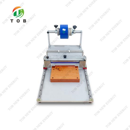
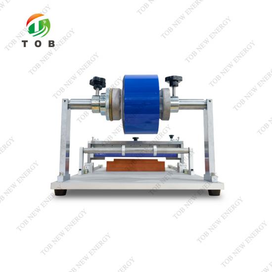
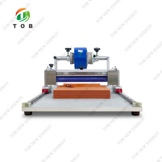
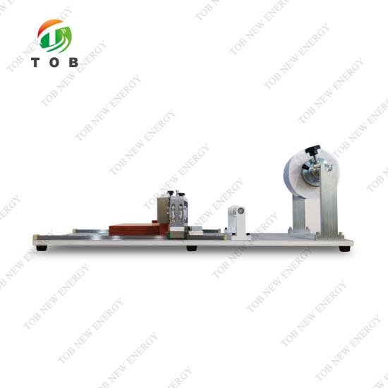
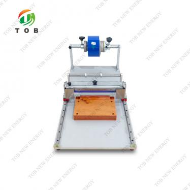
Manual Film Wrapping Machine for Prismatic Cells | TOB-MBFW-300
Brand:
TOB NEW ENERGYitem no.:
TOB-MBFW-300order(moq):
1 setPayment:
L/C,T/Tproduct origin:
Chinashipping port:
XIAMEN
TOB-MBFW-300 Manual Film Wrapping Machine for Prismatic Aluminum-Shell Lithium-Ion Cells
Product Overview and Ideal Applications
The TOB‑MBFW‑300 is a manual film wrapping workstation purpose‑built for applying protective blue insulating film to prismatic aluminum‑shell lithium‑ion cells after the formation process. The wrapping operation provides electrical insulation, mechanical protection, and a clean, uniform appearance to the cell casing before the cell is assembled into a module or pack.
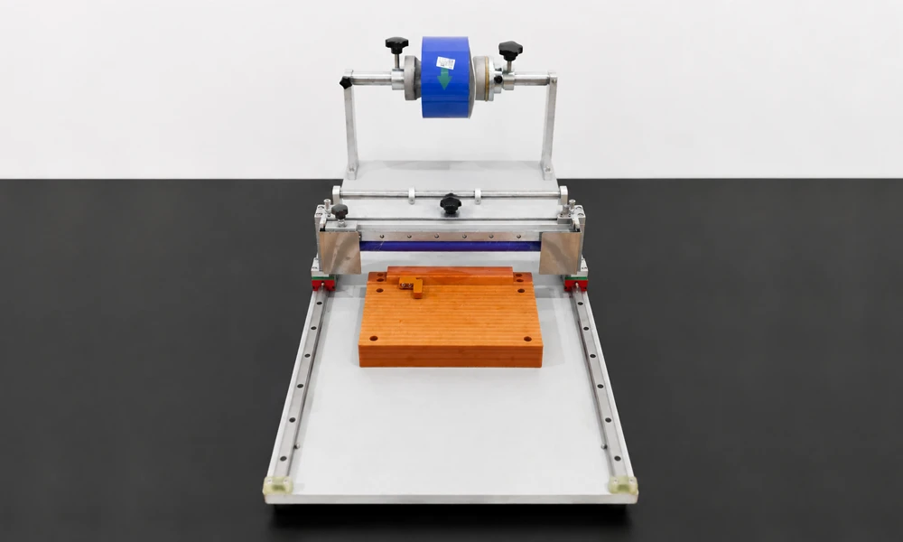
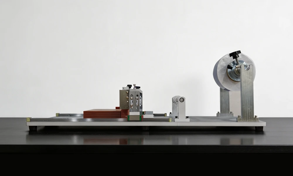
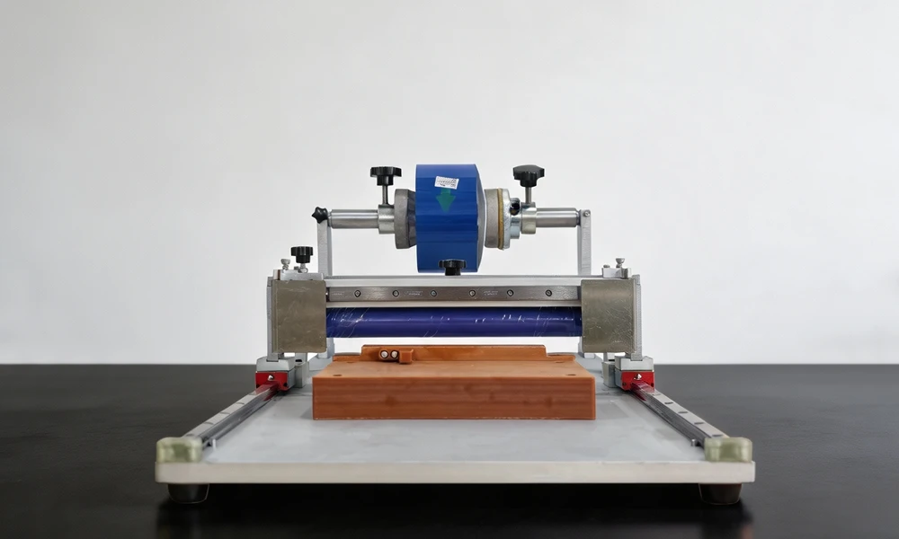
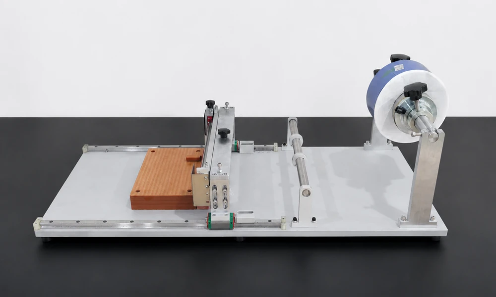
The workstation is designed as a self‑contained benchtop unit (approximately L 1050 mm × W 500 mm × H 450 mm, exact dimensions confirmed by the final design drawing) that integrates all necessary sub‑assemblies for the wrapping process: a film unwind assembly with a support roller and bracket for the blue film roll, guide rollers that maintain flat, wrinkle‑free film travel, an adhesive application module, a film cutting module, and a cell placement platform with edge‑alignment features. The operator places a formed cell onto the platform, pulls the blue film from the unwind roller across the cell surface, applies the film using a smoothing roller, and cuts the film to length. The entire process is performed manually, giving the operator full tactile control over the wrapping quality while the workstation's fixtures ensure repeatable alignment and tension.
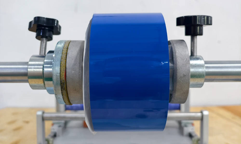
The blue film can be supplied with or without a release liner. The film roll has a core inner diameter of ≤ 77.2 mm and a maximum outer diameter of 400 mm, with a roll weight not exceeding 50 kg. The film unwind assembly is designed so that the roll does not wobble during pulling, the film does not skew under a straight pull (excluding operator misalignment), and the rotation is smooth without jamming. After wrapping, the film overlap is located on the bottom face of the cell, the overlap width is not greater than 2 mm, and the edge lift is less than 0.5 mm. The smoothing roller has an appropriate hardness for film application, is resistant to adhesive build‑up, and is designed for a service life of at least three months under normal production use.
Ideal for:
- Prismatic aluminum‑shell cell production lines where the wrapping step is performed after formation and capacity grading, immediately before cell inspection and module assembly.
- Pilot lines and small‑batch production facilities that need a flexible, manually operated wrapping station that can be quickly changed over between cell models.
- Quality‑focused manufacturers that require precise control over film overlap and edge quality—parameters that directly affect the cell's electrical insulation integrity and its fit into module frames.
Where the Manual Film Wrapping Process Fits in Prismatic Cell Production
In the manufacturing flow for a prismatic aluminum‑shell lithium‑ion cell, the film wrapping step is situated after the formation and capacity grading processes are complete, and before the cell is transferred to the module assembly line or shipped as a finished product. The sequence is typically:
- Cell assembly – Electrode stacking or winding, tab welding, insertion into the aluminum shell, electrolyte filling, and preliminary sealing.
- Formation and grading – First charge and discharge cycles (performed on a formation system such as the TOB‑EF256‑6G for pouch cells, or a prismatic‑cell equivalent), during which the SEI is formed and the cell's capacity is measured and sorted.
- Degassing and final sealing – Removal of formation gases and hermetic closure of the cell.
- Film wrapping (the TOB‑MBFW‑300's role) – Application of the blue insulating film to the outer surfaces of the aluminum shell.
- Final inspection and shipment – Visual check, OCV verification, and packing.
The blue film serves as both an electrical insulator and an identifying feature. It prevents the aluminum shell from creating an unintended conductive path if it contacts another cell's casing or a metal fixture inside the module. The film overlap on the bottom face ensures that the wrap is secure, while the tight edge‑lift specification (< 0.5 mm) prevents the film from catching on handling equipment or peeling back during module insertion.
Because the wrapping is performed manually on the TOB‑MBFW‑300, the operator can visually inspect each cell during the wrapping process and immediately detect any surface irregularity or contamination that might have been introduced in an upstream step. This human quality‑control element is one of the reasons that manual wrapping stations continue to be used even in facilities that have automated most other production steps.
Workstation Components and Operation
The TOB‑MBFW‑300 manual film wrapping machine comprises the following functional modules:
| Module | Function |
| Workbench | The base structure, fabricated from machined components or profiled‑section frame, that supports all other modules. |
| Unwind Assembly | Holds the blue film roll on a roller and bracket assembly. The roll does not wobble, and film pulling (excluding operator misalignment) does not cause skew. Rotation is smooth without jamming. |
| Guide Roller Assembly | Maintains the film in a flat, wrinkle‑free path from the unwind roll to the cell surface. |
| Adhesive Application Module | Applies or activates the adhesive on the blue film, if required for the specific film type being used. |
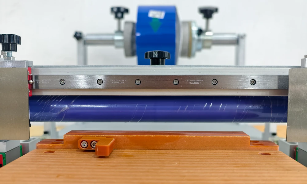
| Film Cutting Module | Cuts the film to the required length after it has been applied and smoothed onto the cell. |
| Cell Placement Platform | A flat platform with edge‑alignment features that position the cell correctly. The platform is made of insulating, corrosion‑resistant material and is sized appropriately for the cell dimensions. |
The operator workflow on the TOB‑MBFW‑300 is:
- Load the cell: Place a formed, graded prismatic cell onto the cell placement platform, aligning it against the edge guides.
- Pull the film: Grasp the free end of the blue film and pull it across the cell surface from the unwind roll. The guide roller assembly keeps the film flat and centred.
- Smooth the film: Use the smoothing roller to press the film onto the cell surfaces. The roller is designed with an appropriate hardness to apply uniform pressure without damaging the cell, and its surface is resistant to adhesive build‑up, allowing it to slide smoothly over the film without sticking.
- Cut the film: Actuate the film cutting module to sever the film at the required length on the bottom face of the cell. The overlap is located on the bottom face by design; the specified overlap width is ≤ 2 mm, and the edge lift after application is < 0.5 mm.
- Inspect and unload: Visually check the wrapped cell for edge quality, wrinkles, and foreign inclusions, and then remove it from the platform.
The smoothing roller is a consumable wear item; the manufacturer specifies a minimum service life of three months under normal production use. Its material and surface treatment are selected to resist degradation from the adhesives used on blue insulating films.
Compatibility with copper‑ and zinc‑free requirements:
Battery production environments often require that all components that may contact the cell be free of copper and zinc‑plated materials, to avoid the risk of metallic contamination that could dissolve into the electrolyte and plate onto the anode. All parts of the TOB‑MBFW‑300 that could contact the cell are manufactured without copper materials and without zinc‑plated (galvanised) finishes.
Key Performance and Quality Specifications
The following specifications define the capabilities and output quality expected from the TOB‑MBFW‑300 in a production environment.
Wrapping Parameter
| Inside diameter of drum | ≤77.2 |
| Blue membrane roll diameter | ≤400mm |
Key Technical Parameters
| Manual wrapping | |
| Blue film feeding |
|
| Wrapping methode |
|
| Overlap zone |
|
| Blue film unwinding |
|
| Cell placement platform |
|
| Roll press |
|
Equipment capability requirements and others
| Equipment capacity (PPM) | Aluminum case battery cell coating+thickness measuring fixture efficiency ≥ 0.5ppm; |
| MTBF (Mean Time Between Failures) | Weekly MTBF ≥ 20h; MTBF=Time of operation within a certain period of time/Number of failures within a certain period of time |
| For this process: weekly MTBF=weekly operation time/weekly failure frequency | |
| Weekly MTBF ≥ (6840min weekly DT)/Weekly failure frequency | |
| The final acceptance should take monthly MTBF as the final acceptance index | |
| MTTR(Mean time to repair) | Weekly MTTR ≤ 20min; MTTR=Failure time within a certain period of time/Number of failures within a certain period of time |
| For this process: weekly MTTR=weekly failure time/weekly failure frequency | |
| Weekly MTTR ≤ Weekly DT/Weekly Failure Times | |
| The final acceptance requires monthly MTBF as the final acceptance indicator | |
| Equipment noise | Equipment noise ≤ 75dB, measured at a distance of 1m from the equipment |
| Design lifespan (excluding vulnerable parts) | ≥5years |
| Prohibition of copper and zinc | Components that may come into contact with the battery must not use copper or galvanized materials |
Cell Compatibility
| Parameter | Dimension |
| Cell Length | 55–65 mm |
| Cell Width | 12–18 mm |
| Cell Height | 80–90 mm |
| Cell Weight | ≤ 2 kg |
Note: The TOB‑MBFW‑300 as delivered is configured for the production of Blueprint 1 cells. All tooling required for Blueprint 1 is included with the shipment. Changeover to other cell models within the compatible range can be performed using the procedures described below.
Changeover and Flexibility
The TOB‑MBFW‑300 supports fast changeover between different cell models within the compatible dimensional range.
- First‑time changeover to a new cell model: Requires one operator; changeover time ≤ 0.3 hours (18 minutes).
- Repeat changeover to a previously run cell model: Requires one operator; changeover time ≤ 0.15 hours (9 minutes).
- Cost: Each changeover incurs only the hardware cost of any replacement tooling and the labour cost of the operator time.
These changeover times allow a single TOB‑MBFW‑300 to serve a pilot line or small‑batch production facility that processes multiple cell form factors within a single shift.
Equipment Configuration List
| No. | Functional Module | Quantity | Remarks |
| 1 | Workbench | 1 set | |
| 2 | Unwind Assembly | 1 | |
| 3 | Guide Roller Assembly | 1 | |
| 4 | Adhesive Application Module | 1 | |
| 5 | Film Cutting Module | 1 | |
| 6 | Cell Placement Platform | 1 |
Spare parts
|
NO. |
Name |
Model |
Quantity |
Remark |
|
1 |
Cell holder |
/ |
1 |
/ |
|
2 |
Internal hexagonal wrench |
Tool set |
1 |
/ |
|
3 |
Flat screwdriver |
6mm*125mm |
1 |
/ |
|
4 |
Flat head screwdriver |
6mm*125mm |
1 |
/ |
Note: All component models and quantities in this table should be provided in full according to the agreement during equipment acceptance
Practical Operation and Maintenance Recommendations
- Film roll loading: Ensure the blue film roll is seated concentrically on the unwind roller and that the core inner diameter (≤ 77.2 mm) matches the roller diameter. An improperly seated roll will wobble and cause the film to skew, leading to angled overlaps and excessive edge lift.
- Smoothing roller inspection: The smoothing roller is the primary wear component. Inspect it daily for adhesive build‑up, surface scratches, or hardening. Clean the roller surface with a suitable solvent (as recommended by the film manufacturer) and a lint‑free wipe. Replace the roller if the surface becomes pitted or if the hardness changes noticeably, as this will affect film adhesion and edge quality.
- Cutting module maintenance: The blade in the film cutting module should be inspected weekly for sharpness. A dull blade will tear rather than cut the film cleanly, producing a ragged edge that is likely to lift. Replace the blade according to the schedule determined by your production volume.
- Cell placement platform: Keep the platform clean and free of adhesive residue. Any debris on the platform can be transferred to the cell surface or the film, creating a visible defect. The platform material is insulating and corrosion‑resistant, so a wipe with isopropyl alcohol is typically sufficient.
- Copper‑ and zinc‑free compliance: All replacement parts and tooling that may contact the cell must conform to the copper‑free and zinc‑free requirement. When ordering spares, specify this to TOB or to your machine shop.
Ready to add a flexible, ergonomic manual film wrapping station to your prismatic cell production line? Request a quotation for the TOB‑MBFW‑300, configured with tooling for your specific cell dimensions. For changeover tooling to additional cell models, contact our production‑tooling engineers.
tob.amy@tobmachine.com | +86 181 2071 5609
You May Also Need
- Prismatic Aluminum Case Battery PET Film Wrapping Machine - An automated or semi‑automated film wrapping system for higher‑throughput prismatic cell production. Complements the manual TOB‑MBFW‑300 by providing a scalable wrapping solution when production volumes increase beyond the capacity of a manual workstation.
- Prismatic Cell Assembly Equipment - Explore TOB's complete range of equipment for prismatic cell assembly—from stacking and winding through tab welding, packaging, and electrolyte filling. Integrates with the TOB‑MBFW‑300 to form a full production line for aluminum‑shell cells.
If you are interested in our products and want to know more details,please leave a message here,we will reply you as soon as we can.

 subscribe to us