Chinese
 français
 Deutsch
 italiano
 español
 português
 Nederlands
 日本語
 한국의




- Home
- >
- Electrode Preparation
- >
- Battery Coating Machine
- >
- Split Type Glove Box Transfer Coating Machine
Categories
Hot Products
Loading...
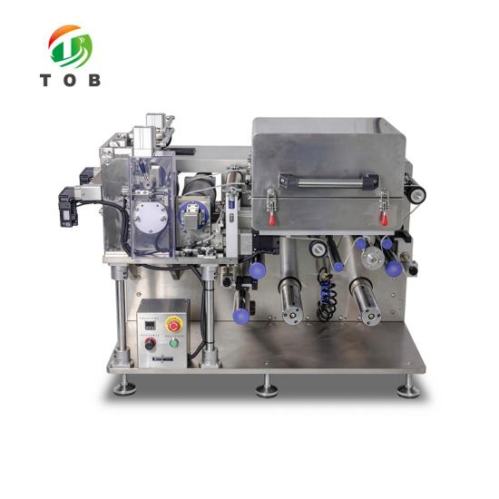
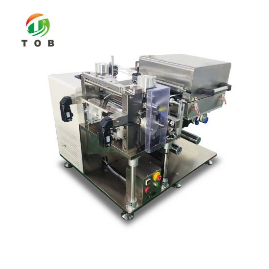
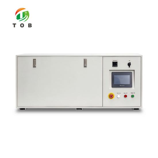
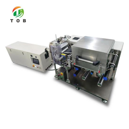
Split Type Glove Box Transfer Coating Machine
Brand:
TOB NEW ENERGYitem no.:
TOB-SY200J-Sorder(moq):
1Payment:
L/C,T/Tproduct origin:
Chinashipping port:
xiamen
Split Type Glove Box Transfer Coating Machine - TOB-SY200J-S
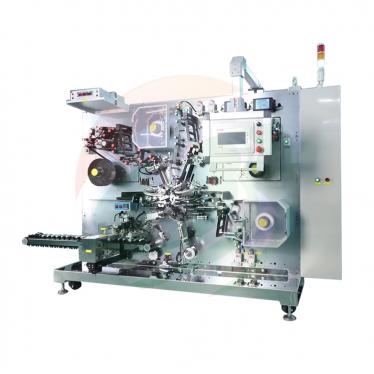
Separate control cabinet, so only the 1270 x 1000 x 950 mm process unit enters the glove box: 200 mm rollers, continuous or intermittent coating, ±3 μm, 0.5 m oven to 150 °C
Product Overview and Ideal Applications
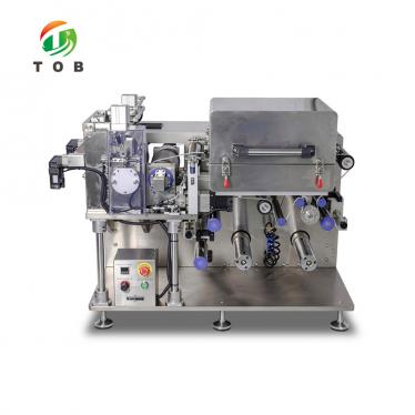
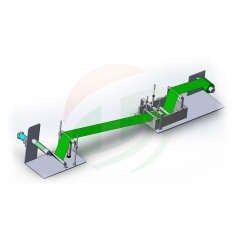
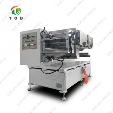
A glove box gives you a fixed port and a small floor, not a factory. The TOB-SY200J-S is built around that limit: the electrical cabinet is a separate 1280 x 450 x 520 mm box that stays outside, and only the 1270 x 1000 x 950 mm process unit goes in. What crosses the box wall is a cable bundle and an air line, not control hardware.
Coating is three-roll transfer, comma blade metered. Continuous and intermittent run on the same head, with coated length from 10 to 5000 mm and blank gaps from 10 to 500 mm, at ±3 μm thickness and 1.5% areal density tolerance. Encoder closed loop holds the pattern, servo blade gap sets the thickness. For wider webs see the roll to roll coating machine for lithium battery electrode.
Drying is a single 0.5 m section, 150 °C maximum, top blowing with bottom side circulation, and 570 m³/h exhaust through an independent port at the oven inlet. In a closed box that port decides whether solvent leaves the box or fills it. Slurry window is 2000 to 12000 mPa·s and 20 to 85% solids.
Ideal for:
- glove box coating, where the control cabinet cannot go inside
- sodium-ion, solid-state and lithium-sulfur work needing dry or inert atmosphere
- laboratories coating 200 mm webs
- intermittent patterns with blank tabs from 10 to 500 mm
- groups carrying a formulation from beaker to a 200 mm roll
Mechanical speed reaches 1 m/min; coating runs at 0 to 0.2 m/min because drying sets the limit.
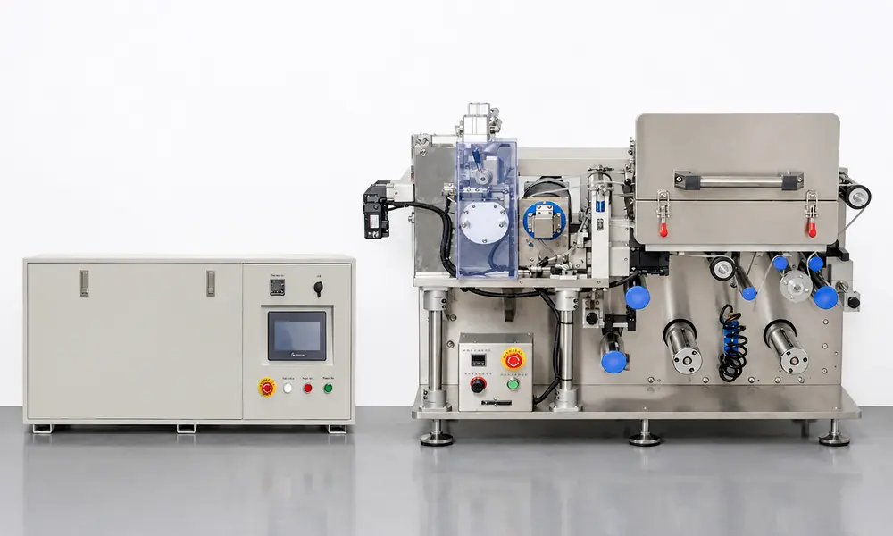
Tell us your glove box port size, the substrate and slurry you run, and the pattern you need. Our engineer will confirm the split layout and the oven exhaust route before the order.
Complete the inquiry form below and our engineer will review your requirements. Prefer email? Contact tob.amy@tobmachine.com
Complete Specifications
Seven tables follow: coating performance, the unwinding and coating head, the oven, the winding end, the control system, dimensions, and the hardware precision that the accuracy figures depend on. Where a figure is a range, the low end is the practical limit and the high end is what the hardware can hold. For a slot die head instead of three roll transfer, the lab slot die coater with 800mm stroke for battery electrode coating is the equivalent machine.
1. Coating performance
| Item | Parameter | Notes |
| Applicable material systems | Vanadium sodium, lithium iron phosphate, lithium cobalt oxide, lithium manganese oxide, graphite, silicon carbon | Cathode and anode formulations |
| Coating mode | Continuous coating, intermittent coating | Three-roll transfer coater |
| Mechanical speed | 1 m/min max | Web travel without coating |
| Coating speed | 0 to 0.2 m/min | Subject to drying performance |
| Coating gap | Coated length 10 to 5000 mm; blank gap 10 to 500 mm | Set on the touch screen |
| Double side gap alignment | Photoelectric detection, automatic gap tracking, reverse side head and tail alignment | For A and B side registration |
| Substrate thickness | Aluminium foil 8 to 30 μm; copper foil 6 to 30 μm | Al and Cu |
| Roller effective width | 200 mm | Coating and glue rollers |
| Guaranteed coating width | 180 mm max | Leaves edge margin on a 200 mm web |
| Coating roller and glue roller diameter | Ø120 mm | Hard chrome plated |
| Doctor roller diameter | Ø100 mm | Comma blade metering |
| Coating thickness accuracy | ±3 μm | Single side |
| Areal density tolerance | ±1.5% or better | Including substrate, excluding edge abnormal zones |
| Applicable slurry viscosity | 2000 to 12000 mPa·s | At coating temperature |
| Single side dry coating thickness | 20 to 200 μm | After drying |
| Solvent compatibility | Oily: NMP, specific gravity 1.033, boiling point 204 °C; aqueous: H2O/NMP, specific gravity 1.000, boiling point 100 °C | Oven and duct material sized for NMP |
| Applicable solid content | 20 to 85% | Slurry |
| Coating dimensional accuracy | Length L ≤ ±1 mm; width W ≤ ±0.5 mm | L length direction, W width direction |
| Front to reverse side registration | L ≤ ±1 mm; W ≤ ±0.5 mm | A side to B side |
| Deviation correction tolerance | ±0.3 mm | Photoelectric edge tracking |
2. Unwinding end and coating head
| Item | Parameter | Notes |
| Guide roller mounting and surface | Rigid steel frame, aluminium rollers with anodized surface | Low inertia, no marking of foil |
| Tension control | Servo motor automatic tension control | Unwinding end |
| Deviation correction | PLC automatic control, 30 mm stroke | Photoelectric sensor |
| Web loading | 3 inch integral rigid air expansion shaft; base on dual slider double row linear guide | High load capacity |
| Unwinding air shaft quantity | 1 piece | Max roll diameter Ø250 mm, max load 50 kg |
| Main drive | Servo motor | Coating and glue rollers servo driven |
| Doctor blade assembly | Double sided comma blade, Ø100 mm alloy steel, hard chrome plated, precision ground | Rigidity and straightness |
| Coating steel roller | Hard chrome plated, double row NSK bearings on both sides | Runout ≤ ±1.5 μm |
| Back up rubber roller | Imported EPDM rubber surface, NSK bearings | Even nip pressure |
| Push back roller motion | Dual servo lead screw control, adjustable gap compensation and travel speed | Tailing adjustable for different viscosities |
| Blade lifting | Dual cylinder lifting for roller cleaning, fine adjustment by precision ball screw linear guide | Gap set by servo |
| Alignment data acquisition | Omron encoder monitors glue roller rotation | Closed loop coating length |
| Head position | Installed upstream of the drying oven | Operator access |
| Agitator unit | Supplied | Prevents slurry sedimentation in the trough |
Three rolls do three jobs: the glue roller picks slurry up, the doctor roller meters it, the coating roller transfers it to the web. The comma blade sets the film on the metering roll, which is why the blade and the coating roller share the same 1.5 μm runout and Ra 0.4 target.
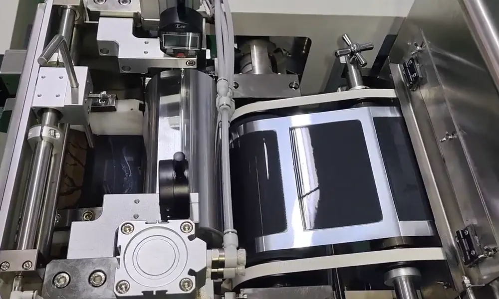
Coating head in operation: comma blade on the metering roll, chrome coating roller against the EPDM back up roller, and one coated patch already visible on the web.
3. Drying oven
| Item | Parameter | Notes |
| Oven construction | Single layer heating with hot air circulation, SUS304 stainless steel | 1 section |
| Oven length | 0.5 m per section | One section on this model |
| Temperature control | Normal control plus overtemperature alarm and protection with main heating circuit cut off; independent control per zone | Omron controller |
| Heating method | Analog signal modulated power with hot air circulation | Control accuracy ±1 °C |
| Heating power | 1.5 kW per section | Solid state relay, analog modulation |
| Oven internal temperature | 150 °C max design temperature; within-section difference ≤ ±2.5 °C | Exhaust air flow 570 m³/h |
| Air blowing mode | Top side blowing, bottom side air circulation | Mould grooved dedicated nozzles |
| Fan | SUS304 stainless steel, contactor control | Inlet and outlet volume by frequency converter |
| Exhaust | Independent exhaust port at oven inlet | Prevents odour leakage into the box |
| Hot air pipe | Ø76 mm | Fast temperature rise |
| Solvent recovery system | Optional accessory | Quoted separately |
4. Winding end
| Item | Parameter | Notes |
| Functions | Identical to the unwinding end, single arm winding up | Rigid steel frame mounting |
| Travelling deviation correction | Installed at the oven outlet | Corrects after drying |
| Tension control | Servo motor automatic tension control | Winding end |
| Winding air shaft quantity | 1 piece | Single arm winding up |
5. Control system
| Item | Parameter | Notes |
| Main control | Touch screen plus PLC plus servo system | Inovance PLC and servo, Weinview HMI |
| Operation modes | Manual, automatic, emergency stop | Selector on the cabinet door |
| Alarm function | Fault prompt pages displayed on the touch screen | Text plus code per fault |
6. Overall dimensions and weight
| Unit | Dimensions (L x W x H) | Net weight |
| Main unit, goes inside the glove box | 1270 x 1000 x 950 mm | 580 kg |
| Electrical cabinet, stays outside | 1280 x 450 x 520 mm | 82 kg |
The main unit is the only part that has to pass the glove box port. Check both footprints against your floor and your port before ordering, not after.
7. Mechanical hardware precision
| Part | Circular runout | Surface and straightness |
| Doctor blade | ≤ ±1.5 μm | Ra 0.4, straightness ≤ ±1.5 μm |
| Coating steel roller | ≤ ±1.5 μm | Ra 0.4, straightness ≤ ±1.5 μm |
| Glue roller | ≤ 10 μm | Straightness ≤ 10 μm |
These three numbers are the floor under the ±3 μm coating figure. A blade that runs out by 5 μm cannot hold a 3 μm tolerance, whatever the control system does.
Electrical and Mechanical Components
The control chain is Inovance end to end, with Omron for temperature and position, Panasonic for sensing, and NSK and HIWIN/TBI under the moving parts. The list below is what the drawing specifies, not a preference list.
| Item | Brand | Item | Brand |
| PLC | Inovance | Temperature controller | Omron |
| Touch screen | Weinview | Encoder | Omron |
| Servo motor | Inovance | Optical fiber and sensors | Panasonic |
| Frequency converter | Inovance | Electronic pressure gauge | Panasonic |
| Stepper motor | Leadshine | Intermediate relay | IDEC |
| Planetary reducer | Neugart | Electrical control components | IDEC / Chint |
| Bearing | NSK | Power regulator | Longke |
| Fan | Sanyue | Power supply | Mean Well |
| Pneumatic components | Airtac | Linear guide and lead screw | HIWIN / TBI |
| Coating roller | Hard chrome plated | Back up roller | EPDM rubber |
| Guide roller | Aluminium alloy, anodized | Automatic deviation correction | Photoelectric |
| Automatic tension control | Servo motor driven | Main roller and glue roller drive | Servo motor driven |
To meet delivery requirements the supplier reserves the right to substitute a component with an equivalent-grade part, provided the rated performance in the tables above is unchanged. Tell us at enquiry stage if your own qualification or spare-parts policy fixes a brand, and it will be confirmed in the order specification.
Key Engineering Characteristics
- Split is the design, not an option. The electrical cabinet is a separate 1280 x 450 x 520 mm unit at 82 kg. Only the 1270 x 1000 x 950 mm process unit at 580 kg is meant to sit inside the glove box, so the box floor carries the coating hardware and nothing else.
- The operator stands outside. Touch screen, run mode selector and emergency stop are on the cabinet door, so recipes are set and the machine is started with the box closed and the gloves untouched.
- 200 mm rollers, 180 mm guaranteed width. The 20 mm difference is the edge margin that keeps slurry off the coating roller ends and keeps the uncoated foil clean for the tab. Above this width the automatic film coating and drying machine, 300 and 400 mm stroke takes over.
- Pattern held by encoder, thickness held by servo. Coating length comes from an Omron encoder on the glue roller in closed loop, 10 to 5000 mm coated with 10 to 500 mm gaps; blade gap is set by servo, which is what the ±3 μm and ±1.5% figures rest on.
- Three roll transfer gives a wide process window. 2000 to 12000 mPa·s, 20 to 85% solids, 20 to 200 μm dry thickness on one side, which is where a lab formulation usually sits before it is optimised.
- Dual servo push back roller. Gap compensation and travel speed are set separately, so tailing can be adjusted for a thin anode slurry and a thick cathode slurry without changing the blade.
- Oven exhaust leaves the box. 570 m³/h through an independent port at the oven inlet, 0.5 m of heating at 150 °C maximum with a within-section spread of ±2.5 °C, so NMP is carried out rather than circulated into the atmosphere.
- Solvent recovery is separate. The recovery unit is an optional accessory, because whether you need one depends on your duct and your local emission rules, not on the coater.
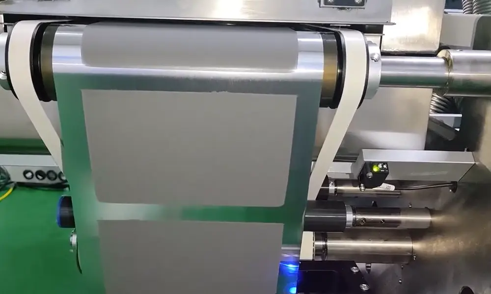
Finished intermittent cathode coating on aluminium foil, blank gaps left for the tab. The photoelectric sensor at the oven outlet tracks the edge on the way to winding.
Why the Control Cabinet Is Separate
A control cabinet is not a passive box. It holds the frequency converters, the solid state relays, the power regulator and the power supply, and those are the parts that get warm. Inside a sealed glove box that heat has nowhere to go: it warms the atmosphere you paid to dry and purify, and the box then has to remove it. Moving the cabinet outside removes the heat load at the source instead of fighting it with the purifier.
The second reason is service. Almost every fault on a coater is diagnosed at the cabinet, with a meter and a wiring diagram. If the cabinet sits inside the box, a blown fuse means breaking atmosphere, waiting for the antechamber cycle, and working in gloves on parts you cannot see properly. Outside, the same fault is a bench job while the box stays under vacuum or under argon.
The third is space and load. The cabinet adds 1280 x 450 x 520 mm and 82 kg. On a laboratory floor that is trivial; inside a box it is the difference between fitting and not fitting, because the constraint is the port and the antechamber, not the room. 82 kg that never has to be lifted through a port is 82 kg that cannot damage a flange on the way in.
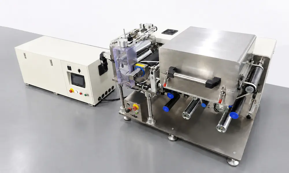
Cabinet at the left, process unit at the right, seen from the winding end. The two are linked by a cable bundle, so the port only has to pass cables and the air line.
Splitting also changes who runs the machine. The touch screen is on the cabinet, so the recipe is entered outside the glass. An operator does not have to open the box to change the coated length from 300 mm to 450 mm, and a run is not interrupted by a pair of gloves reaching across a moving web.
The trade off is planning. A split machine needs a cable route and a proper earth between the two units, the 570 m³/h exhaust has to be ducted out of the box, and the compressed air line has to reach the head. None of that is difficult, but it has to be decided before the machine arrives, not after it is inside. Send us the port size and the duct route and we will confirm the layout against them.
Installation, Utilities and Safety
1. Room and box conditions
| Zone | Temperature | Relative humidity |
| Machine head | 25 to 30 °C | ≤ 35% RH for cathode, ≤ 98% RH for anode |
| Other zones | 10 to 40 °C | ≤ 98% RH |
The head figures are the ones that matter, and they are the reason the machine belongs in a box: a cathode slurry on aluminium foil will pick up moisture between the blade and the oven inlet in an ordinary room. The oven and the winding end are far less sensitive, which is why they carry the wider range.
2. Utilities
| Utility | Requirement |
| Power supply | 3 phase five wire, 380 V, 50 Hz, voltage fluctuation +10% to -10% |
| Total starting power | 5 kW |
| Compressed air | Dried, filtered and stabilised, outlet pressure ≥ 0.5 MPa |
| Exhaust | 570 m³/h ducted out of the glove box from the independent port at the oven inlet |
The cabinet takes the 380 V feed outside the box. Only the low voltage bundle and the air line cross the wall, which is why the port stays small.
3. Safety and handling
- The main unit is 580 kg and the cabinet 82 kg. Plan the lift points and the route into the box before the delivery date, and keep the unit on its feet rather than on a roller during the move.
- Bond both units to the same earth. A split machine with two enclosures and one earth reference is safer than two floating enclosures joined by a signal cable.
- NMP at 204 °C boiling point is the solvent the oven is built for. Keep the exhaust connected whenever the oven is hot, even during a trial run, and keep the solvent recovery unit, if you buy one, on the same duct.
- The emergency stop is on the cabinet door. Anyone working inside the box needs a second way to stop the machine, planned with your own box safety system.
- Isolate power and air before opening the cabinet or reaching into the coating head. The blade lift cylinders hold pressure after the air is off.
Certification, Patents and Research Record
1. CE position for this model
We hold two 2024 CE certificates for transfer coating machines, issued in May 2024 by CAC Conformity Assessment Center d.o.o. in Zagreb: M.2024.206.C00026 under the Low Voltage Directive 2014/35/EU, and M.2024.206.C00047 under the Machinery Directive 2006/42/EC and the EMC Directive 2014/30/EU. Their model column lists 19 designations, among them TOB-SY300J, TOB-SY300-2J, TOB-SY400J, TOB-JYCM-250/300/800 and the TOB-VFC series. TOB-SY200J-S is not one of those 19 designations, so this page does not claim CE marking for it. If your import requires CE on this exact model, say so in the enquiry and we will confirm what the certificate scope allows before you order.
2. Management system certificates
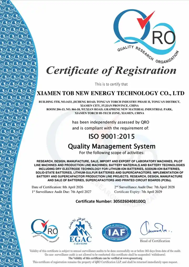
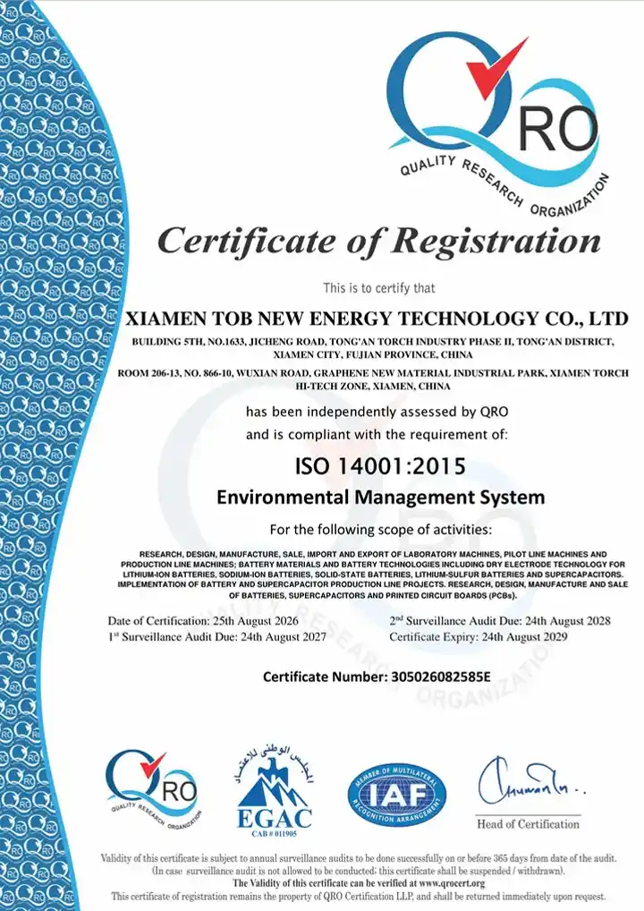
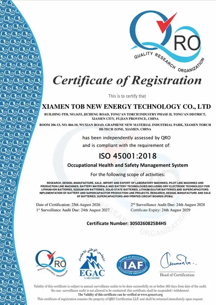
The plant that builds the TOB-SY200J-S holds ISO 9001 under 3050260408100Q, issued 8 April 2026 and valid to 7 April 2029, together with ISO 14001 (305026082585E) and ISO 45001 (305026082584HS).
|
|
|
3. Patents on coating machines
Dany Huang, Ph.D., founder and CEO, entered the industry in 2002 and founded TOB NEW ENERGY in 2012. Of the 55 Chinese patents he holds as of September 2026, three are drawn on coating machines: CN215429971U laboratory-scale battery coating machine, filed 9 September 2021; CN215542414U, a lithium battery coating machine with a continuous feeding device, filed 1 September 2021; and CN215612935U, a liftable heating device for lithium battery coating machines, filed 1 September 2021. The first is the family this model comes from: a small coating machine built for laboratory use.
4. Research record
Our citation index holds 707 records, 70 of which name a specific TOB model. One record names TOB-SY300J, the 300 mm version of this transfer coater. None names the TOB-SY200J-S. We separate the two numbers on purpose: the series has been used and cited, this designation has not, and we would rather you know which is which than read an average.
5. Reference projects
Two builds show where a coater of this class sits. The sodium-ion battery lab line project is the closest match, because a sodium-ion line is planned around moisture and oxygen the same way a glove box is. The 60138 supercapacitor pilot line project is the scale-up step, where the same coating logic runs on wider rollers. Neither project page specifies this model.
Engineering FAQ
Q1: Can the control cabinet go inside the glove box as well?
It can physically be put there, but it should not be. The cabinet carries the frequency converters, solid state relays and power supply, and it adds 1280 x 450 x 520 mm and 82 kg to what the box has to hold. Keep it outside and the box only has to deal with the coating process, not with the electronics that run it.
Q2: What port size and utilities do I need to prepare?
Only the main unit passes the port: 1270 x 1000 x 950 mm at 580 kg. The cabinet stays outside, so the port does not have to clear it. On the utility side, plan a 380 V three phase five wire feed at 5 kW starting power, dry filtered air at 0.5 MPa or more, and a duct for 570 m³/h of exhaust. Send the port dimensions and we will check the unit against them before the order is fixed.
Q3: Is the TOB-SY200J-S CE marked?
Not under the certificates we hold today. The 2024 transfer coater certificates name 19 designations in the SY, JYCM, VFC and W400 families; this model is not among them. If your import needs CE marking on this exact designation, raise it in the enquiry so the scope can be confirmed before shipment rather than after arrival.
Q4: What coating speed can I actually run?
0 to 0.2 m/min for coating, against a 1 m/min mechanical maximum. The gap between the two is drying: the oven is 0.5 m long, so at 0.2 m/min the web spends 2.5 minutes inside it, and at 0.05 m/min it spends 10 minutes. If your slurry needs more than 2.5 minutes to dry, the machine will run slower than its rated coating speed, and no amount of mechanical speed changes that.
Q5: Can one machine coat both cathode and anode?
Yes, within the 2000 to 12000 mPa·s and 20 to 85% solids window. What differs is the atmosphere: the head is specified at 35% RH or below for cathode and 98% RH or below for anode, and that limit is set by the slurry rather than by the hardware. If your box runs dry for cathode, the same head coats anode without a change of parts.
Q6: How is the intermittent pattern set and held?
The pattern is entered on the touch screen as coated length and blank gap, 10 to 5000 mm and 10 to 500 mm, and held in closed loop by the Omron encoder on the glue roller. Blade lifting is by dual cylinder for cleaning, with the working gap set by servo on a ball screw linear guide, so a pattern change does not require touching the blade by hand.
Send the glove box port size, the substrate and slurry you run, and the pattern you need, and we will confirm the split layout, the exhaust route and the oven length against them.
Email: tob.amy@tobmachine.com | Mobile phone: +86-18120715609
Reviewed by: Science Wang, Six Sigma Black Belt, Battery Lines | Last updated: 2026-11-16
Previous:
Continuous Doctor Blade Coating Machine For Battery ElectrodeNext:
Dual-Mode Battery Electrode Coating Machine (Slot Die & Transfer)
If you are interested in our products and want to know more details,please leave a message here,we will reply you as soon as we can.

 subscribe to us